Systems and methods for thermal management in a gas turbine powerplant
a technology of thermal management and gas turbine power, which is applied in the direction of machines/engines, turbine/propulsion fuel heating, instruments, etc., can solve the problems of varnish or coke deposits that can foul the combustor fuel nozzle, oil jet, and other fuel, control, lubrication, and the temperature of engine fuel to exceed the operational limit, so as to reduce the effect of engine fuel temperature, increasing the temperature limit of fuel, and reducing coke deposition
- Summary
- Abstract
- Description
- Claims
- Application Information
AI Technical Summary
Benefits of technology
Problems solved by technology
Method used
Image
Examples
first embodiment
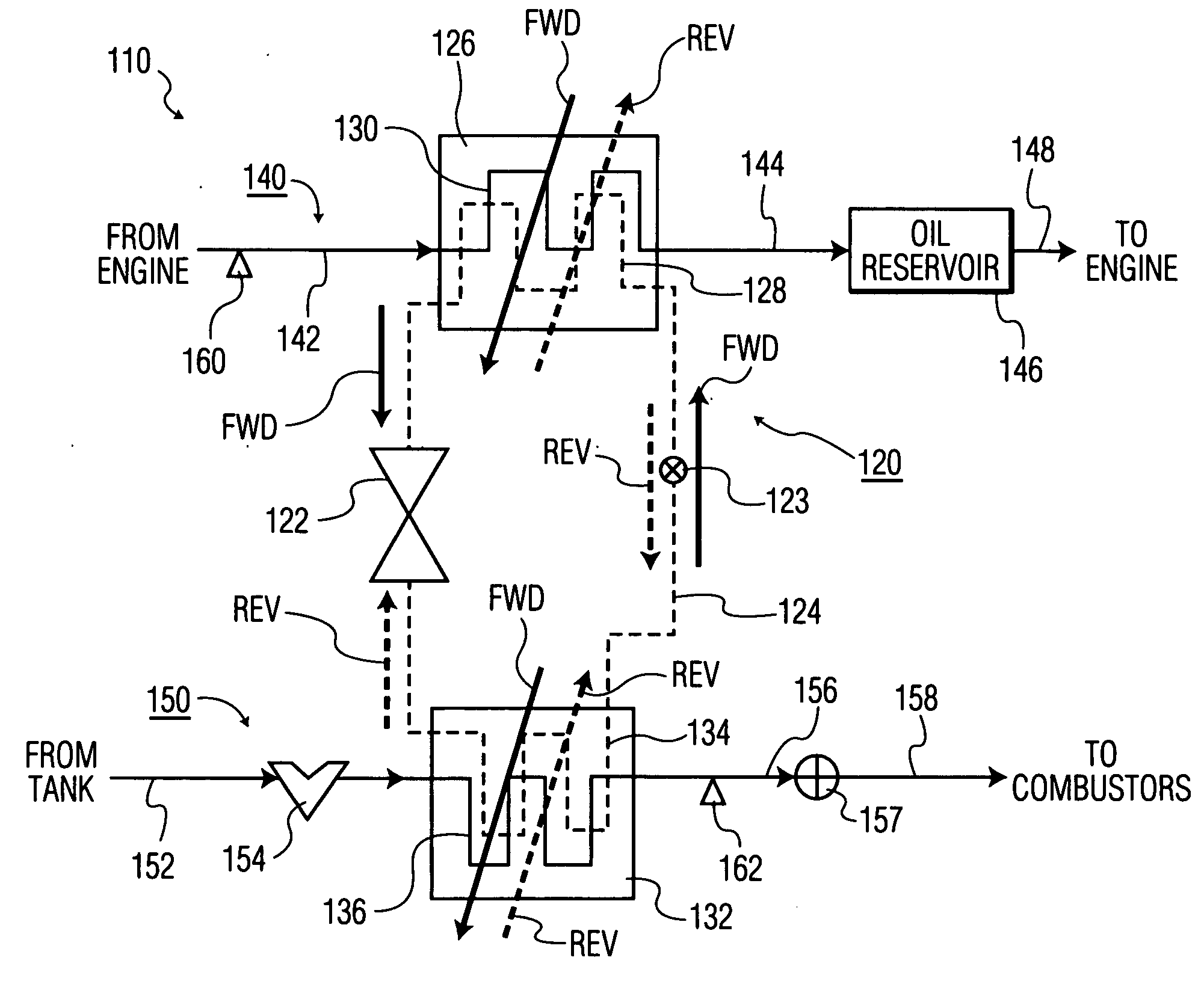
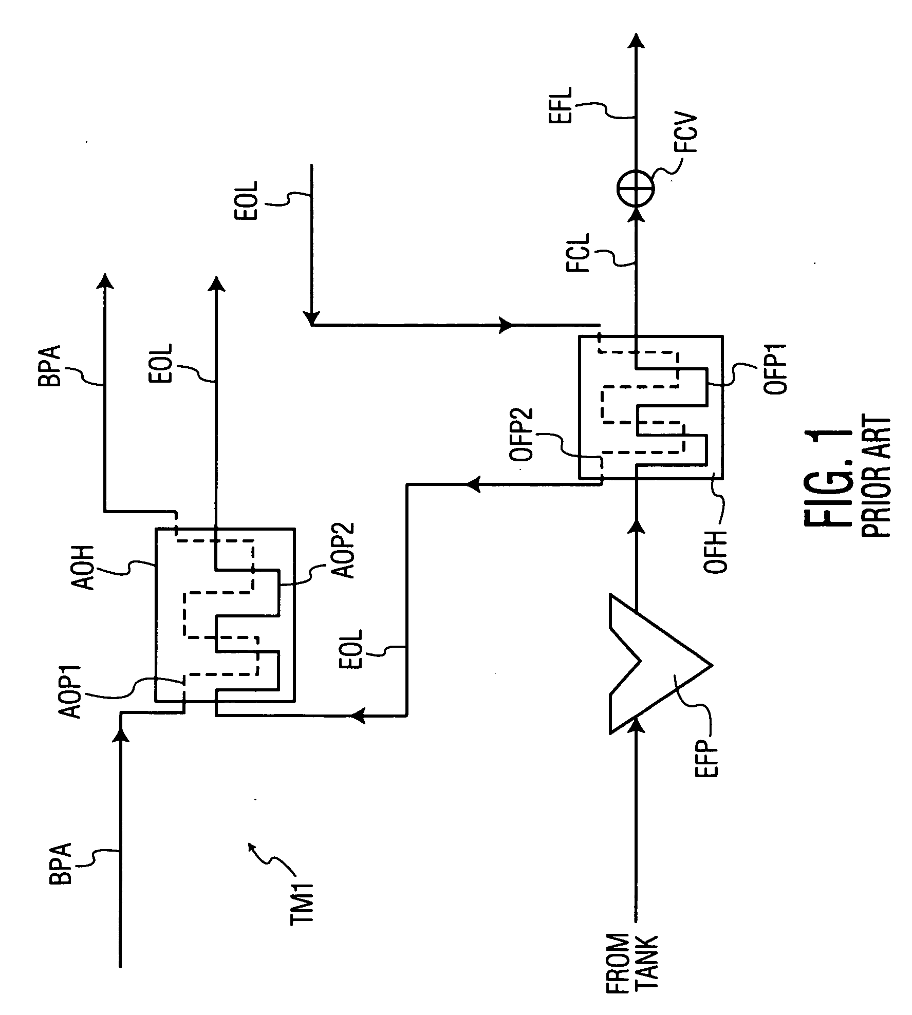
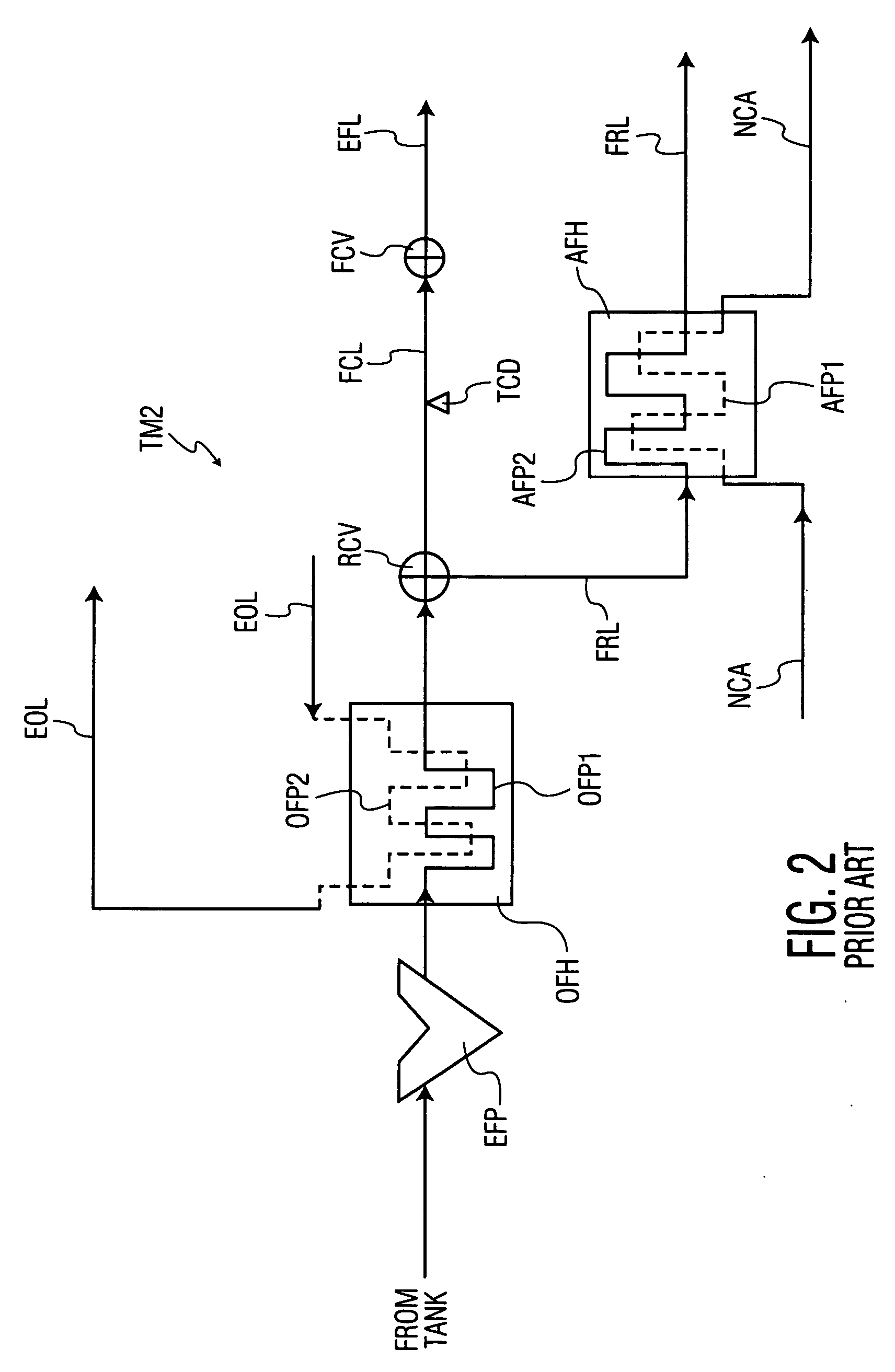
[0032]FIG. 4 is a schematic depiction of the invention incorporating a basic building block of a thermal management system according to the present invention. This basic building block comprises a heat transfer control module with a reversible heat pump that circulates a working fluid through at least two heat exchangers. This module can be included in myriad thermal management systems to optimize thermal management for particular apparatus such as gas turbine aircraft engines like those described above in connection with FIGS. 1 to 3. By employing a reversible heat pump, the present invention provides significantly improved operational flexibility that enables the heat transfer characteristics of the system to be more precisely controlled and more readily tailored to a particular engine across a greater range of operating conditions. When used in combination with a reservoir for a lubricant that circulates through the apparatus, as described below, the system includes a thermal cap...
second embodiment
[0045]FIG. 5 illustrates a thermal management system 210 according to the invention, in which a heat transfer control module 220 is used in cooperation with a conventional fuel re-circulation system such as the one depicted in FIG. 2. In the embodiment shown in FIG. 5, components that represent counterparts of components shown in FIG. 4 are given a “200” series reference number. In that same regard, components in FIG. 5 are constructed and operate in a fashion similar to corresponding components in FIG. 4, as described in detail above. Accordingly, one skilled in this art will readily understand the construction and operational principles of the heat transfer control module 220 in FIG. 5 by reference to the description above in connection with FIG. 4, and for that reason the following description focuses mainly on the differences between the systems shown in FIGS. 4 and 5.
embodiment 210
[0046]A basic difference between the thermal management system 110 shown in FIG. 4 and its counterpart embodiment 210 shown in FIG. 5 is that the fuel exit line 256 from the second heat exchanger 232 leads to a fuel recirculation subsystem 280, and more particularly to a fuel re-circulation valve 282 of the fuel recirculation subsystem. The valve 282 corresponds to the valve RCV shown in FIG. 2. One output of the valve is an exit fuel line 284 that leads to a fuel control valve 257, from which an engine fuel line 258 supplies fuel to the engine combustors. A second outlet of the valve 282 leads to a fuel recirculation line 286. The fuel recirculation line 286 is introduced to an auxiliary heat exchanger 288 with a first heat exchange path 290 for the fuel, the outlet of which re-introduces the fuel to the engine fuel tank. A second heat exchange path 292 accepts a small portion of the inlet or nacelle air flow, as described in connection with the systems depicted in FIG. 2. More par...
PUM
 Abstract
Description
Claims
Application Information
 - R&D
- Intellectual Property
- Life Sciences
- Materials
- Tech Scout
- Unparalleled Data Quality
- Higher Quality Content
- 60% Fewer Hallucinations
Browse by: Latest US Patents, China's latest patents, Technical Efficacy Thesaurus, Application Domain, Technology Topic, Popular Technical Reports.
© 2025 PatSnap. All rights reserved.Legal|Privacy policy|Modern Slavery Act Transparency Statement|Sitemap|About US| Contact US: help@patsnap.com


