
IC die having TSV and wafer level underfill and stacked IC devices comprising a workpiece solder connected to the TSV

a technology of integrated circuits and workpieces, which is applied in the direction of semiconductor devices, semiconductor/solid-state device details, electrical apparatus, etc., can solve the problems of difficult attachment to workpieces, difficult underfill processing, and general underfill voids, so as to reduce assembly time and reduce cost , the effect of low throughpu

Active Publication Date: 2010-04-22
TEXAS INSTR INC
View PDF35 Cites 50 Cited by
  • Summary
  • Abstract
  • Description
  • Claims
  • Application Information

AI Technical Summary

Benefits of technology

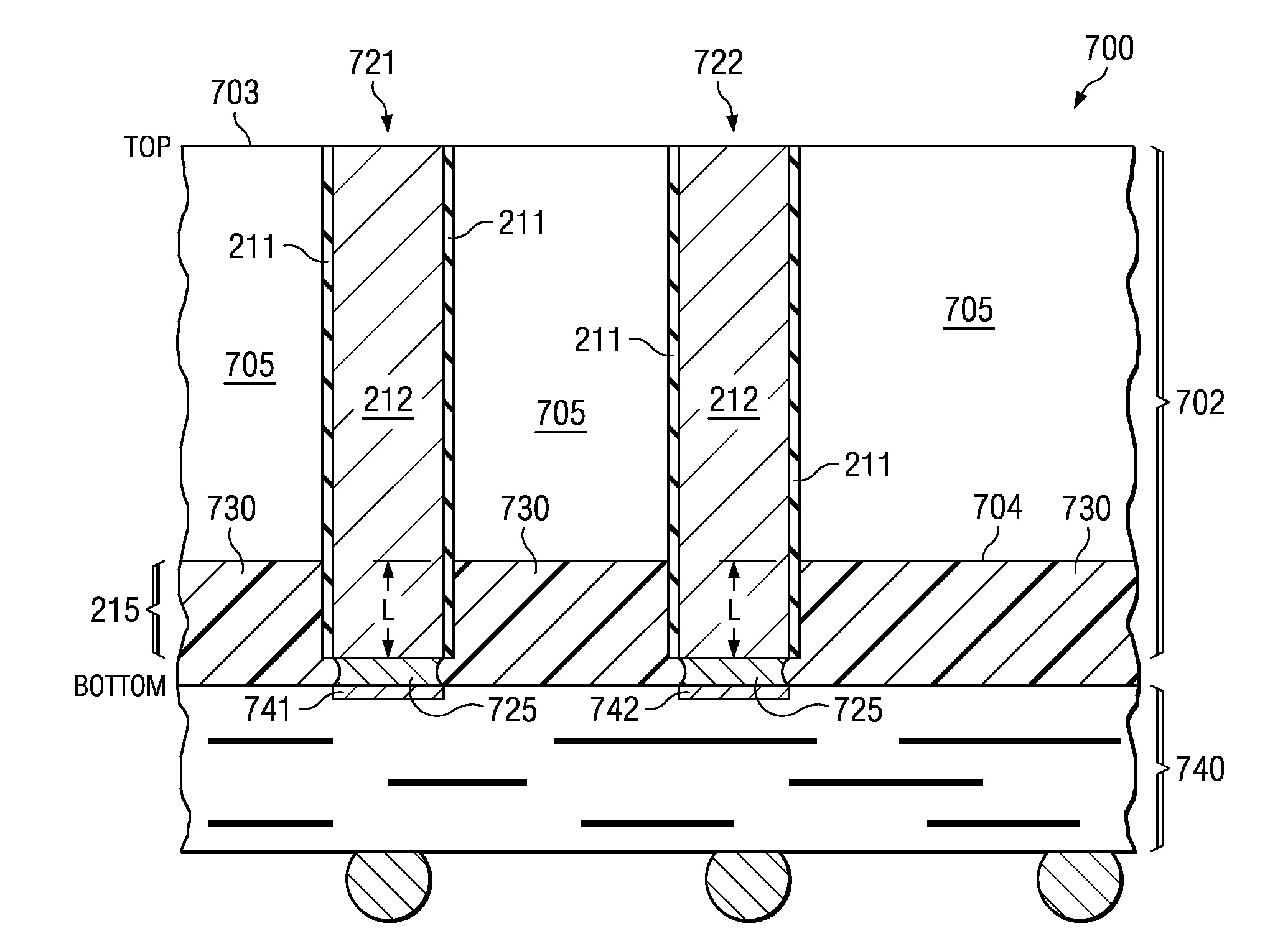
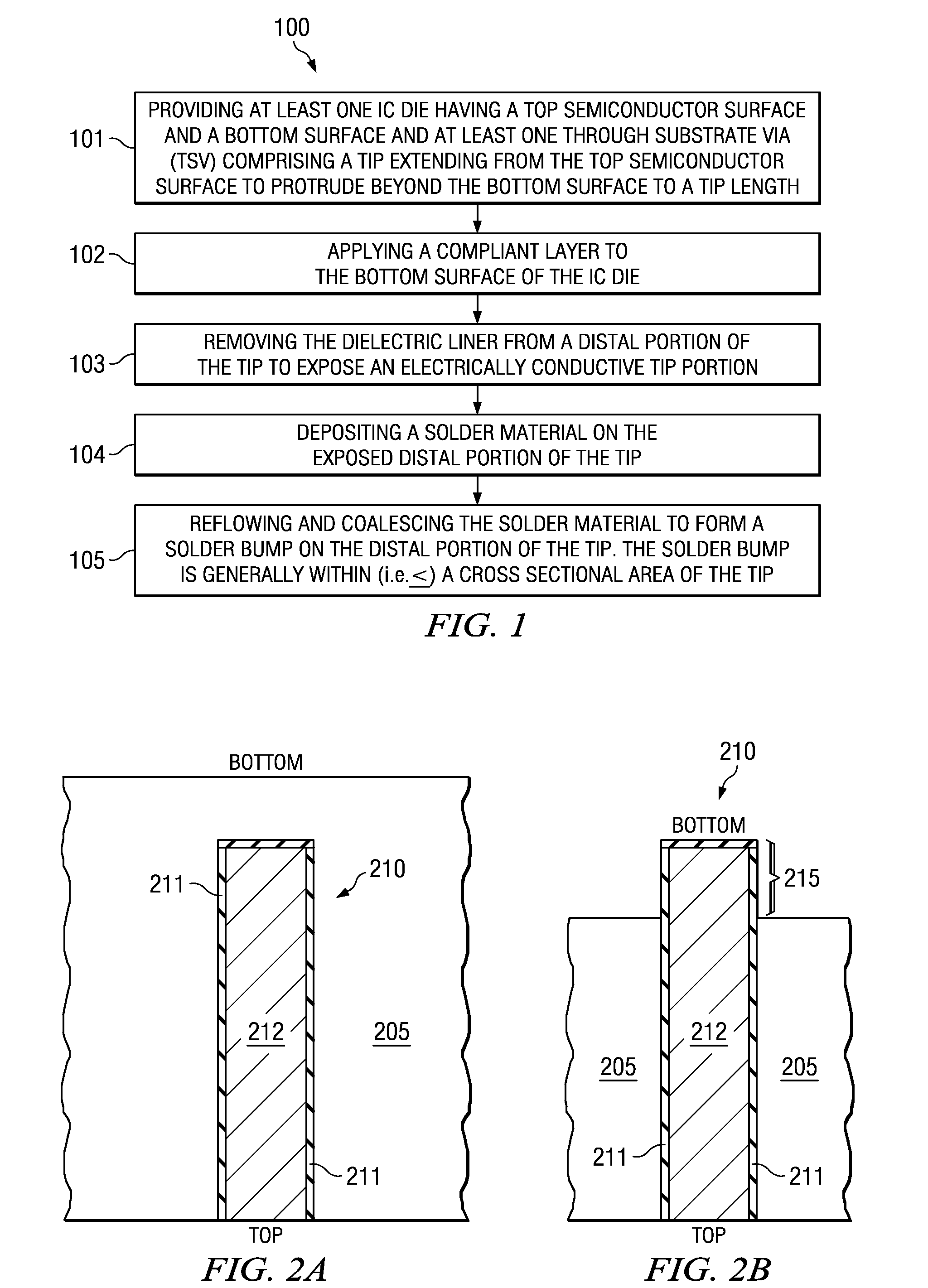
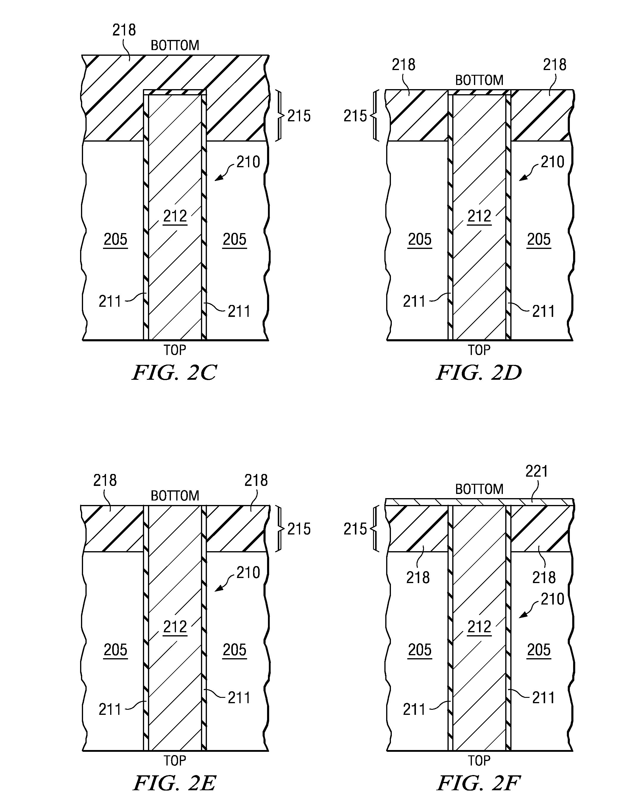
[0007]Embodiments of the present invention describe processing comprising applying a compliant layer at the wafer level as part of the TSV exposure process, thus eliminating the need to apply conventional underfill at the package level. This aspect of embodiments of the invention eliminates the above-described difficulty in filling small gaps, and eliminates a package level process step which is typically low throughput, thus reducing assembly time and reducing cost.
[0008]A relatively small and controlled amount of a solder material is applied to the distal end of the TSV tip at the wafer or die level which is then used to create the solder joint during the package assembly process. Better control of the amount of solder applied provided by embodiments of the invention have been found to improve joint formation leading to fewer shorted or open connections as compared to conventional processing. Generally, a photodefinable masking material is applied at the die or wafer level to deposit a small, well controlled amount of solder on the distal end of each TSV tip. The masking material is allowed to remain behind (non-sacrificial) and serves as underfill in the final device between the IC die containing the TSV and the workpiece that generally comprises another die or a package substrate. Embodiments of the invention generally include solder reflow processing. Reflow of the solder allows a very thin applied or a small solder ball to coalesce into a thicker dome shaped solder bump which facilitates die alignment and solder joint formation.

Problems solved by technology

The Present Inventors have realized that assembly of IC die having a plurality of TSVs including some relatively fine pitched TSVs having a small stand-off distance between the IC die and the workpiece (e.g., package substrate or other IC die) that they are attached to, generally makes conventional underfill processing difficult.
As a result, underfill voids generally result.
Moreover, the very small size of the TSVs (e.g., 10 to 30 μm diameter, or less) renders them difficult to attach to a workpiece using conventional approaches that rely on a solder coating on the workpiece.
Moreover, since the attach pads of the workpiece are typically larger in area as compared to the TSV cross sectional area dimension (e.g., diameter), solder volume is difficult to control, often resulting in shorts between neighboring TSVs (e.g., when there is too much solder) or open connections (e.g., when there is not enough solder).

Method used


Image

  • IC die having TSV and wafer level underfill and stacked IC devices comprising a workpiece solder connected to the TSV
  • IC die having TSV and wafer level underfill and stacked IC devices comprising a workpiece solder connected to the TSV
  • IC die having TSV and wafer level underfill and stacked IC devices comprising a workpiece solder connected to the TSV

Examples


Embodiment Construction

[0017]The present invention is described with reference to the attached figures, wherein like reference numerals are used throughout the figures to designate similar or equivalent elements. The figures are not drawn to scale and they are provided merely to illustrate the instant invention. Several aspects of the invention are described below with reference to example applications for illustration. It should be understood that numerous specific details, relationships, and methods are set forth to provide a full understanding of the invention. One having ordinary skill in the relevant art, however, will readily recognize that the invention can be practiced without one or more of the specific details or with other methods. In other instances, well-known structures or operations are not shown in detail to avoid obscuring the invention. The present invention is not limited by the illustrated ordering of acts or events, as some acts may occur in different orders and / or concurrently with o...


PUM


Abstract

A method of forming integrated circuit (IC) die configured for attachment to another die or a package substrate, and stacked IC devices therefrom. At least one IC die having a top semiconductor surface and a bottom surface and at least one through substrate via (TSV) including a tip protruding beyond the bottom surface to a tip length is provided. The tip has an outer dielectric tip liner, and an electrically conductive portion within the outer dielectric tip liner. A compliant layer is applied to the bottom surface of the IC die. The dielectric tip liner is removed from a distal portion of the tip to expose an electrically conductive tip portion. A solder material is deposited on the exposed distal portion of the tip. The solder material is reflowed and coalesced to form a solder bump on the distal portion of the tip.

Description

CROSS REFERENCE TO RELATED APPLICATIONS[0001]This application claims the benefit of Provisional Application Ser. No. 61 / 106,065 entitled “Semiconductor Packages”, filed Oct. 16, 2008, which is herein incorporated by reference in its entirety.FIELD OF THE INVENTION[0002]Embodiments of the present invention relate to integrated circuits (IC) devices having through substrate vias and packaged ICs.BACKGROUND[0003]Some ICs include through silicon vias (TSVs) which are also referred to as through wafer vias (TWS). Due to their considerably shorter length as compared to conventional wire bond connections, TSVs reduce inductance and resistance and thus improve IC performance.[0004]As known in the art of semiconductor package assembly, in conventional assembly processing for ICs that comprise TSVs, solder regions are applied to the workpiece which can comprise a package substrate (e.g. printed circuit board (PCB)) or other IC die. The IC is aligned such that the TSV tips are aligned to the s...

Claims


Application Information

Patent Timeline
IPC IPC(8): H01L25/065H01L21/60H01L23/488
CPCH01L21/76898H01L23/481H01L2924/0002H01L2924/00014H01L2924/1461H01L2224/0401H01L2224/05571H01L2224/0557H01L23/5384H01L24/11H01L24/12H01L24/16H01L25/0657H01L25/50H01L2224/114H01L2224/1147H01L2224/1148H01L2224/116H01L2224/13021H01L2224/13025H01L2224/13099H01L2225/06513H01L2225/06541H01L2924/01015H01L2924/01029H01L2924/01074H01L2924/01075H01L2924/01078H01L2924/01082H01L2924/14H01L2924/30107H01L2924/01005H01L2924/01006H01L2924/01033H01L2924/014H01L2924/00012H01L2924/00H01L2224/05552H01L2924/12042
Inventor SIMMONS-MATTHEWS, MARGARET R.ABBOTT, DONALD C.
Owner TEXAS INSTR INC
Learn More