Liquid contactor and method thereof
a liquid contactor and contactor technology, applied in the direction of fuel gas production, transportation and packaging, separation processes, etc., can solve the problems of limited control of concentration gradient, prone to clogging and breakage, and serious clogging problems, and achieve low pressure sorbent operation, large volumetric mass transport coefficient, and small size
- Summary
- Abstract
- Description
- Claims
- Application Information
AI Technical Summary
Benefits of technology
Problems solved by technology
Method used
Image
Examples
example 1
[0088]In Example 1, a single jet test apparatus was utilized to illustrate how water exits a nozzle under normal operating conditions. The apparatus is described with reference to FIGS. 7A-7C.
[0089]Referring to FIGS. 7A-7C, the apparatus is generally depicted as reference number 700 and includes an operating chamber 702, a liquid inlet 704, a fluid exit 708, a gas inlet 713 and a gas exit 714. The fluid exit 708 is connected to a recirculation loop and coupled to a pump (not shown) and the fluid inlet 704. A pressure gauge (not shown) is mounted for measuring fluid pressure in a plenum 709 above a nozzle plate 712. The plenum is a sealed chamber formed above the plate 712 and has dimensions of 226 mm wide by 28.5 mm tall by 20 mm deep. The nozzle plate 712 includes three nozzle banks 714, 716, and 718. In this configuration each nozzle bank includes three nozzles. In particular, nozzle bank 716 includes a first nozzle 720, a second nozzle 722, and a third nozzle 724. Each nozzle is ...
example 2
[0093]In Example 2, an array of jets was formed with the test stand apparatus of FIG. 8A. The system is generally depicted as reference number 800. The system 800 includes a fluid catch basin 802, a fluid pump 804, and tubing connecting the single nozzle bank 806. Fluid flowed in a recirculation manner from the catch basin 802 to the pump and though the nozzle bank 806 to produce flat jets 808 that were recaptured in the catch basin. The tubing from the pump was tied just upstream of the nozzle bank to allow feeding from both sides of the nozzle bank. A pressure gauge 810 was placed on the fluid line at the tee to measure fluid pressure supplied to the nozzle bank.
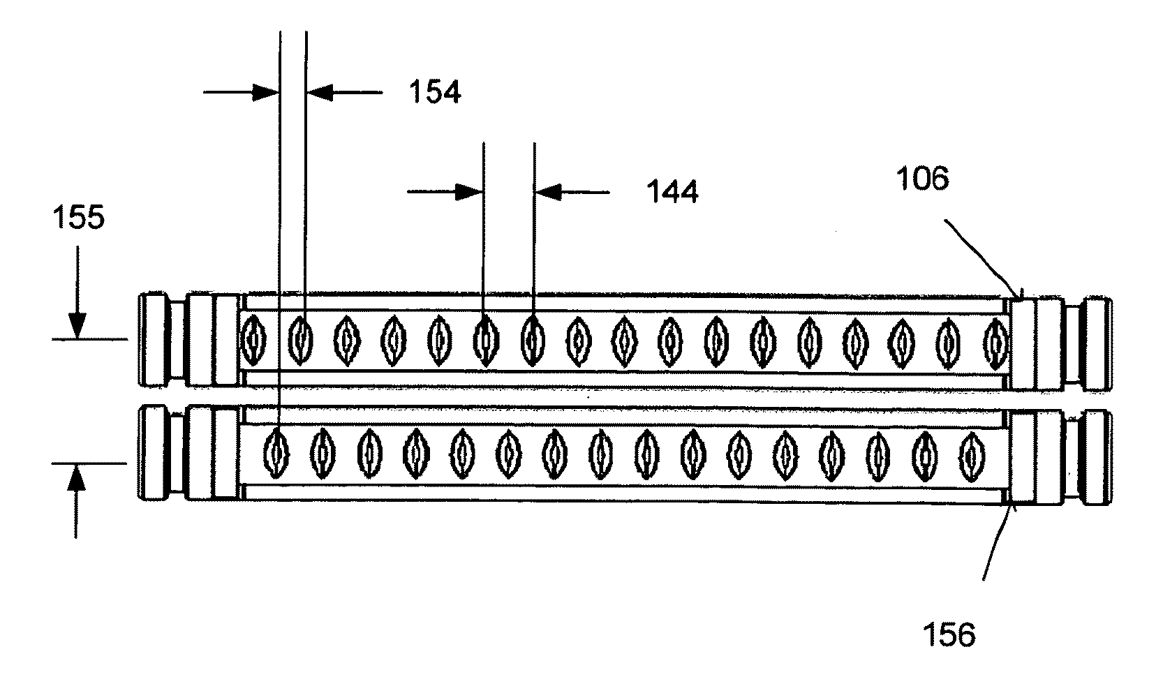
[0094]FIG. 8B illustrates a nozzle bank used in Example 2. The nozzle bank is generally depicted as reference number 812. The nozzle bank 812 was formed from an 8 inch long, 0.5 inch diameter stainless steel tube. A 4 inch middle portion 814 of the tube was compressed to form a 0.375 inch wide ellipse. The nozzle bank incl...
example 3
[0097]In Example 3, an array of jets was formed with the test stand apparatus of Example 2. For this Example, the nozzle bank 812 was modified with a channel insert as shown in FIGS. 10A-10B.
[0098]FIG. 10A illustrates a cross-sectional perspective view of a channel insert according to Example 3. FIG. 10B illustrates a cross-sectional perspective view of a channel insert of FIG. 10A taken along line B to B′.
[0099]Referring to FIGS. 10A-10B, the channel insert is generally depicted as reference number 1000. The channel insert 1000 was fastened to an inside wall of the nozzle bank 812 by set screws (not shown) through the opposing nozzle bank wall. The channel insert 1000 was formed from an aluminum block. A plurality of channels 1002 were machined into the block to match the corresponding nozzle openings in the nozzle bank 812. The individual channels 1002 in the insert were formed to be about 0.039 inches in width, about 0.175 inches in length, and about 0.19 inches in depth. The edg...
PUM
| Property | Measurement | Unit |
|---|---|---|
| Length | aaaaa | aaaaa |
| Length | aaaaa | aaaaa |
| Fraction | aaaaa | aaaaa |
Abstract
Description
Claims
Application Information
 - R&D
- Intellectual Property
- Life Sciences
- Materials
- Tech Scout
- Unparalleled Data Quality
- Higher Quality Content
- 60% Fewer Hallucinations
Browse by: Latest US Patents, China's latest patents, Technical Efficacy Thesaurus, Application Domain, Technology Topic, Popular Technical Reports.
© 2025 PatSnap. All rights reserved.Legal|Privacy policy|Modern Slavery Act Transparency Statement|Sitemap|About US| Contact US: help@patsnap.com


