
Techniques for time transfer via signal encoding

a signal encoding and signal technology, applied in the field of telecommunications systems, can solve the problems of not being well suited to applications requiring precise synchronization, difficulty in real-time or timing sensitive applications that require synchronization, and network technologies facing. achieve the effect of high bit transition density

Inactive Publication Date: 2010-04-01
RPX CLEARINGHOUSE
View PDF11 Cites 33 Cited by
  • Summary
  • Abstract
  • Description
  • Claims
  • Application Information

AI Technical Summary

Benefits of technology

"The patent describes techniques for transferring time through signal encoding. These techniques involve generating a time service ordered-set and a time service data for inclusion in a physical coding sublayer frame of a physical layer device. The physical coding sublayer frame is then transmitted. The time service ordered-set may be a single special code-group or a sequence of code-groups. The time service data may have high bit transition density, disparity control, or coding distance. The technique may be used in computer processes or apparatuses for time transfer via signal encoding. The patent is useful for those working in fields that require efficient time transfer."

Problems solved by technology

One of the biggest hurdles packet networking technologies face in replacing traditional Time Division Multiplexing (TDM) systems in both core and access networks is the transmission of accurate timing information (time and / or frequency).
However, a problem occurs when a backhaul connection transitions to Ethernet, thus isolating the remote and access elements from their source of synchronization.
While Ethernet has proven to be a useful, inexpensive, and ubiquitous technology for connectivity, it has not been well suited for applications requiring precise synchronization.
By nature, it is asynchronous, which creates difficulty for real-time or timing sensitive applications that require synchronization.
The first is timing errors introduced by instabilities and drift of local oscillators, and the second is fluctuations in path delay (commonly know as delay variation) between transmitter and receiver clocks.
Oscillator stability is primarily a component selection issue for a system designer.
The primary sources of delay variations are due to Layer 2 and higher impairments such as queueing delays in network devices, media contention delays, software protocol stack processing delays, operating system and other software tasks delays, etc.
Delay variation significantly degrades clock synchronization because it introduces variability to the travel time of timing protocol messages.
Under normal non-congested loading conditions on the network path, a fraction of the total number of packets will traverse the network at or near this floor, even though some may experience significantly longer delays.
However, a major limitation of this approach is that, at higher loads, minimum delay screening and selection of messages at end nodes will simply produce poor clock quality since a very small fraction of timing messages will experience the minimum “intrinsic” propagation delay of the network path.
In view of the foregoing, it may be understood that there may be significant problems and shortcomings associated with current clock synchronization technologies.

Method used


Image

  • Techniques for time transfer via signal encoding
  • Techniques for time transfer via signal encoding
  • Techniques for time transfer via signal encoding

Examples


Embodiment Construction

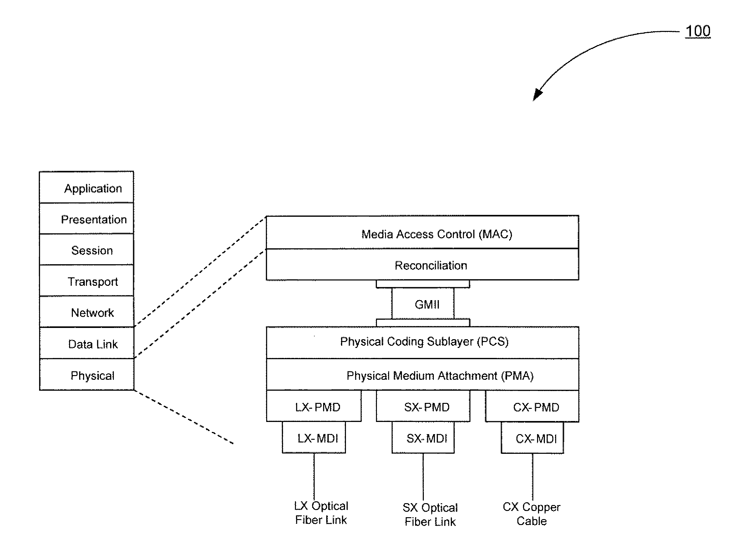
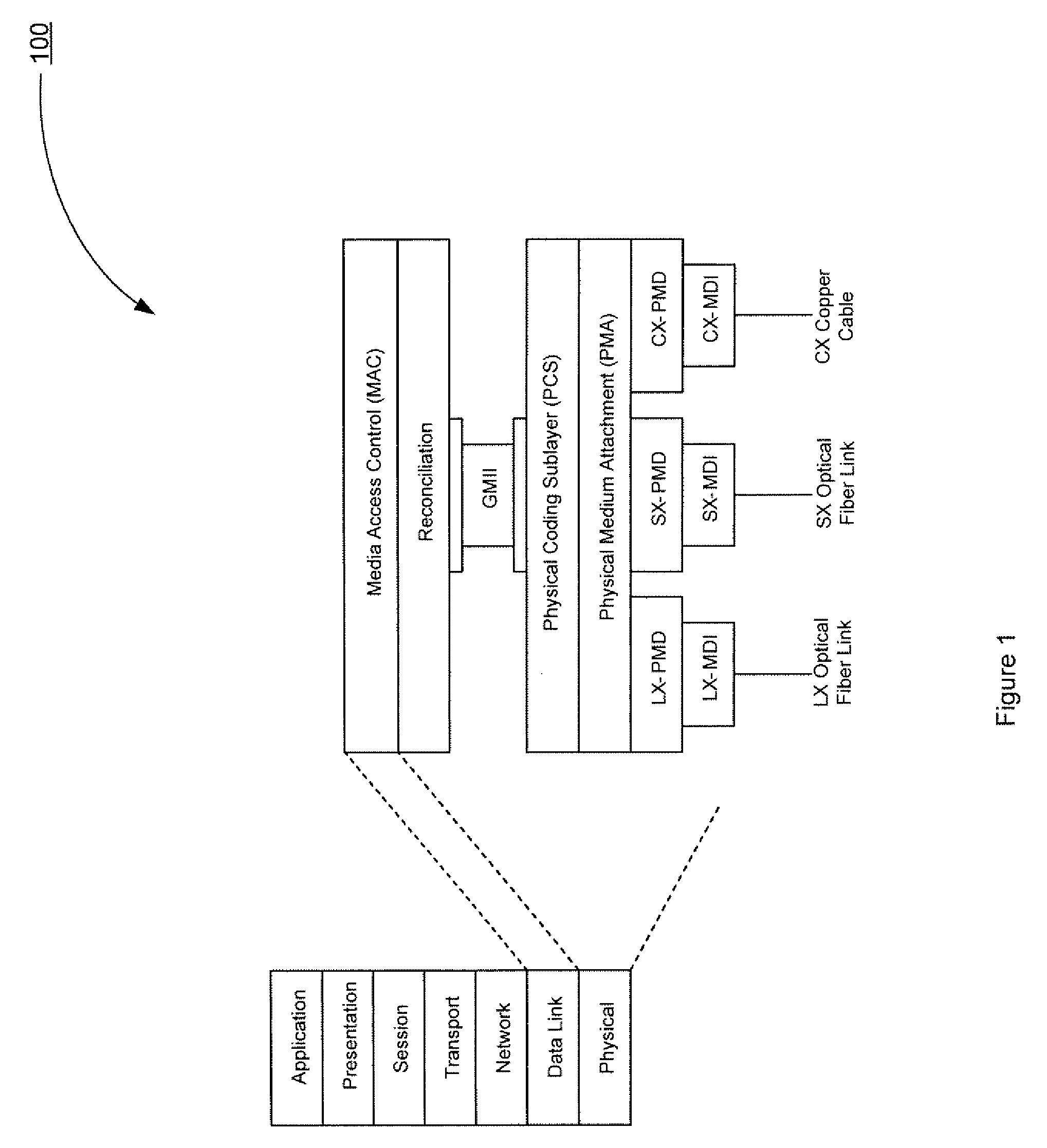
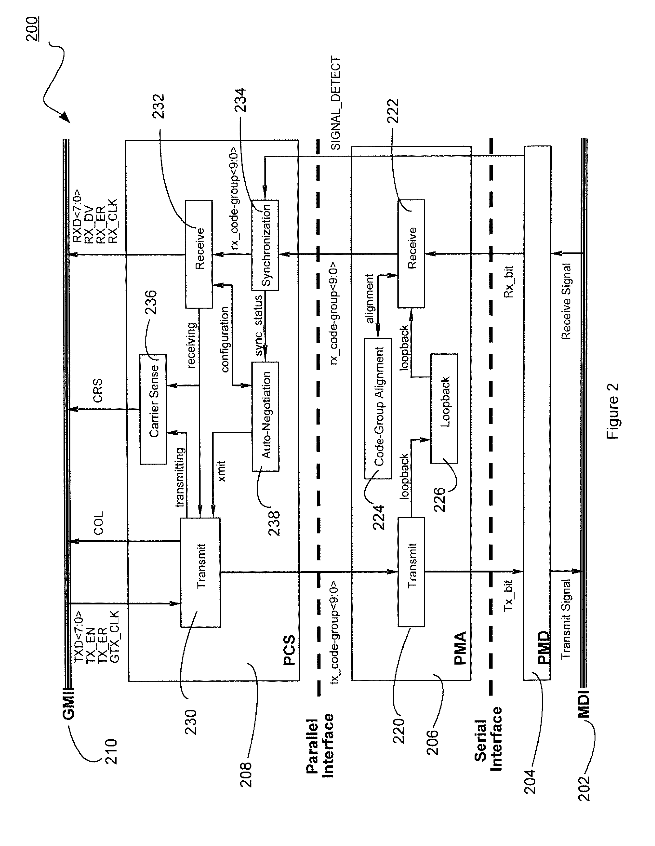
[0040]The present disclosure relates to enhancements to a Physical Layer of Gigabit Ethernet that enable accurate distribution of time and frequency. In accordance with the present disclosure, network slave devices may synchronize to a master reference time source (or server) using a messaging protocol. The messaging protocol may be a ranging technique by which the slave devices (or clients) may estimate their time offsets from the master time reference. The slave devices may accomplish this by exchanging a series of timestamped messages at the Physical Layer with a central time server.

[0041]A Physical Coding Sublayer (PCS) of the Physical Layer of Gigabit Ethernet may map Gigabit Medium-Independent Interface (GMII) signals into 10-bit code-groups, and vice-versa, using an 8B / 10B block coding scheme. The PCS may accept packets from a Reconciliation sublayer via the GMII and encode a packet before passing it to a Physical Medium Attachment (PMA) sublayer. The PCS may also decode a bi...


PUM


Abstract

Techniques for time transfer via signal encoding are disclosed. In one particular exemplary embodiment, the techniques may be realized as a method for time transfer via signal encoding comprising generating a time service ordered-set for inclusion in a physical coding sublayer frame of a physical layer device, generating time service data for inclusion in the physical coding sublayer frame of the physical layer device, and transmitting the physical coding sublayer frame.

Description

CROSS-REFERENCE TO RELATED APPLICATIONS[0001]This patent application claims priority to U.S. Provisional Patent Application No. 61 / 101,802, filed Oct. 1, 2008, which is hereby incorporated by reference herein in its entirety.FIELD OF THE DISCLOSURE[0002]The present disclosure relates generally to telecommunications systems and, more particularly, to techniques for time transfer via signal encoding.BACKGROUND OF THE DISCLOSURE[0003]Time and / or frequency distribution is a fundamental requirement for packet networks. One of the biggest hurdles packet networking technologies face in replacing traditional Time Division Multiplexing (TDM) systems in both core and access networks is the transmission of accurate timing information (time and / or frequency). Legacy TDM networks were designed to carry precise frequency synchronization throughout their respective networks. But increasingly, access systems such as wireless base stations and multi-service access nodes (MSANs) require synchronizati...

Claims


Application Information

Patent Timeline
Patent Type & Authority Applications(United States)
IPC IPC(8): H04J3/06
CPCH04J3/0682H04J3/0697H04J3/065H04L67/06H04W56/0055H04L7/04
Inventor AWEYA, JAMESOUELLETTE, MICHEL
Owner RPX CLEARINGHOUSE
Learn More