
Extraction electrode manipulator

a technology of extraction electrodes and manipulators, which is applied in the field of ion implantation systems, can solve the problems of suppression electrodes in the extraction area in a very hostile environment, suppression electrodes having to endure frequent and high voltage sparks, and sputter coating

Inactive Publication Date: 2010-03-25
AXCELIS TECHNOLOGIES
View PDF4 Cites 19 Cited by
  • Summary
  • Abstract
  • Description
  • Claims
  • Application Information

AI Technical Summary

Benefits of technology

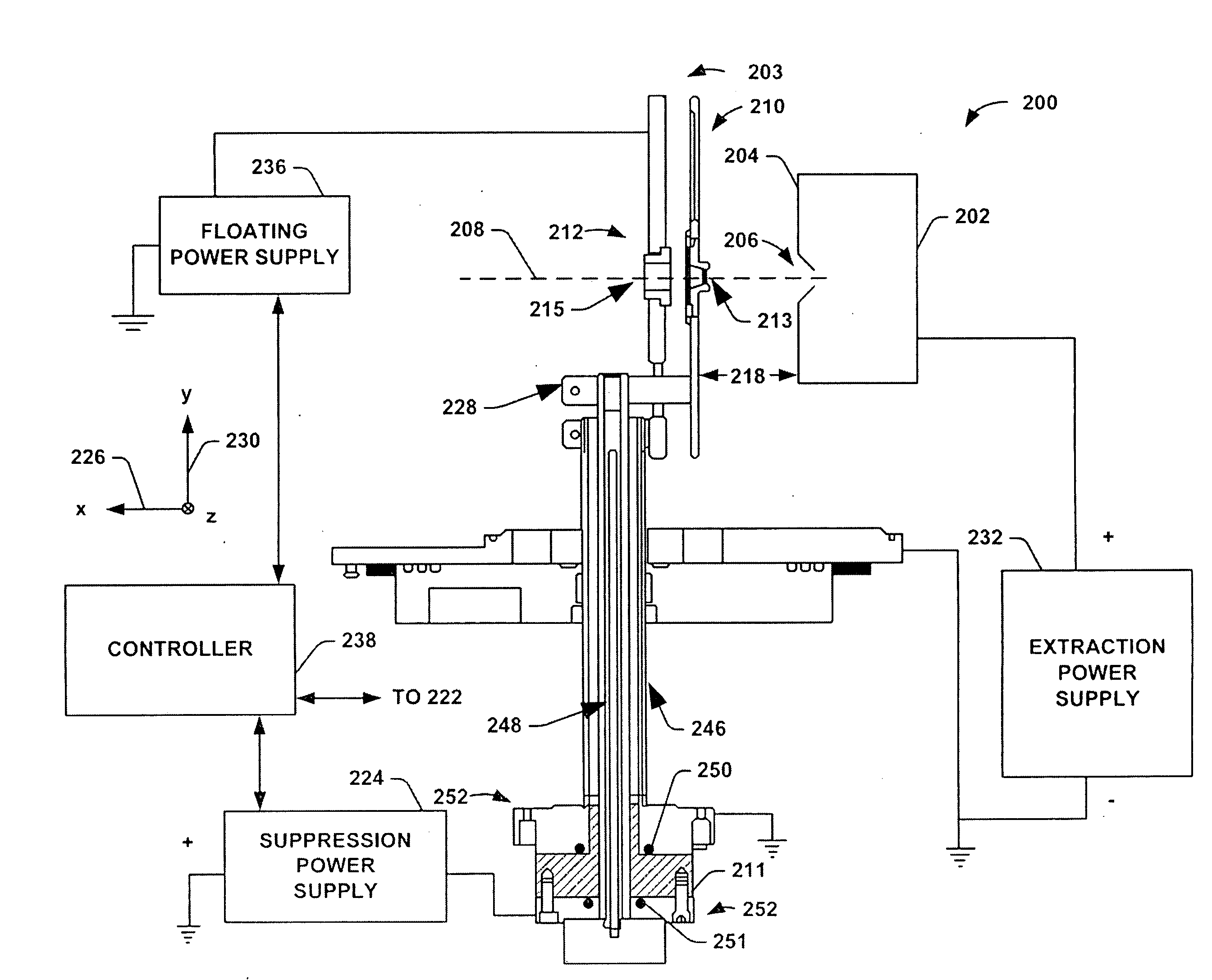
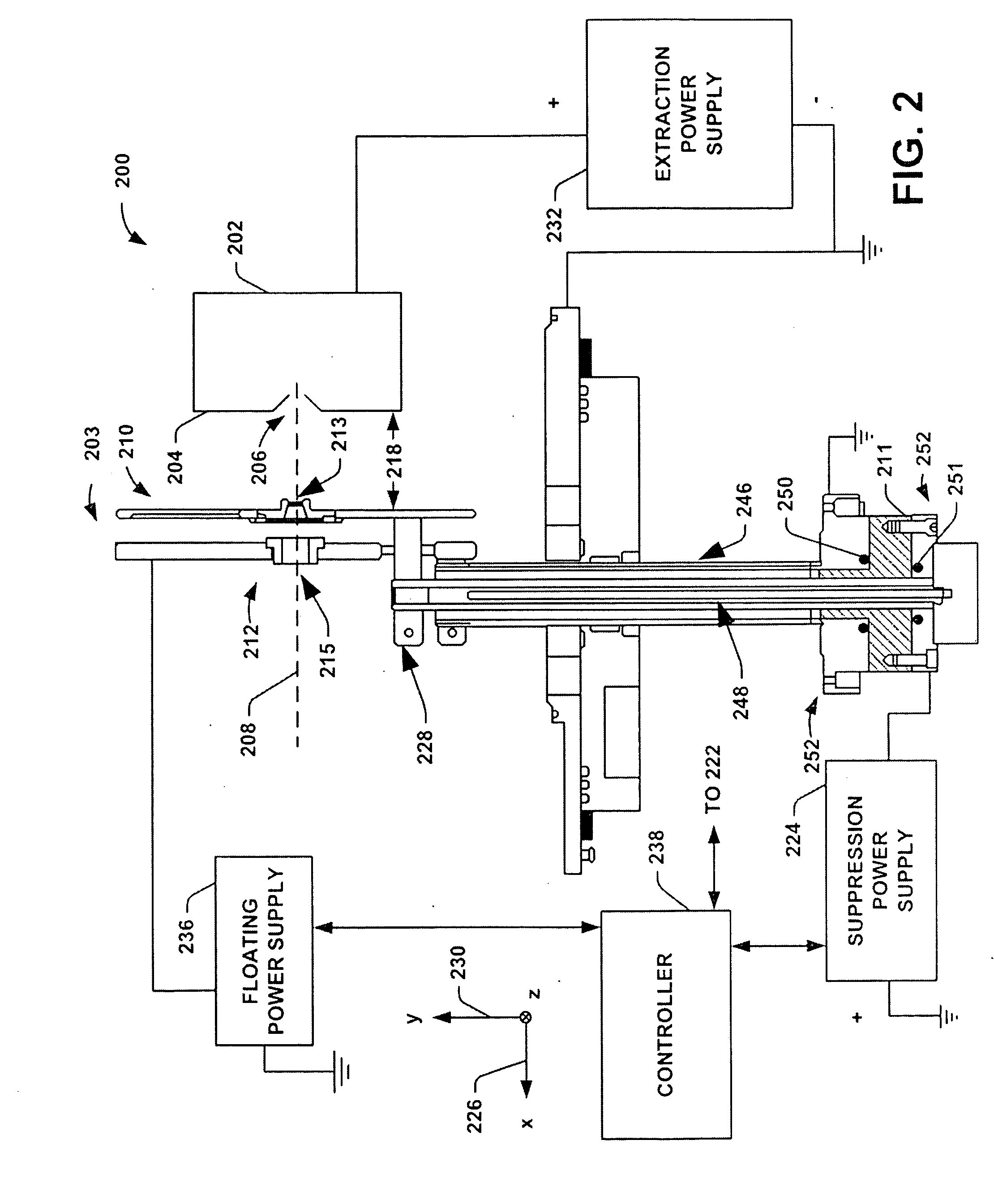
[0010]The present invention is generally directed to eliminate high voltage insulating standoffs and high voltage feedthrough from close vicinity to the ion source, where their insulating property tends to deteriorate quickly because of surface coating, and move them, combine them, into one insulator far away from the dirty environment.

Problems solved by technology

The suppression electrode in the source extraction area is in a very hostile environment.
First, the high energy, high flux ion beam causes sputtering of electrode and aperture materials (i.e., mostly metal and carbon) to coat unshielded insulative surfaces to make the surfaces conductive or in addition, build up conductive “flakes” which can and often eventually cause problems, for example, initiating high voltage sparks.
Secondly, the vacuum environment is known to be a “dirty location”, often containing condensable vapor from within an ion source feed material and the vapor can “snake” through elaborate shielding structures to coat or deposit on the “hidden” insulative surface.
Thirdly, related to the two reasons mentioned above, the suppression electrode has to endure frequent and high voltage sparks with large energy release (e.g., several Joules).
Although typical ceramic standoffs are well protected by layer(s) of metal shields, those high voltage sparks often induce secondary sparks in the hidden insulative areas to cause sputter coating even in those hidden areas and worse case, insulators can crack because of a sudden surge current and rapid heating.
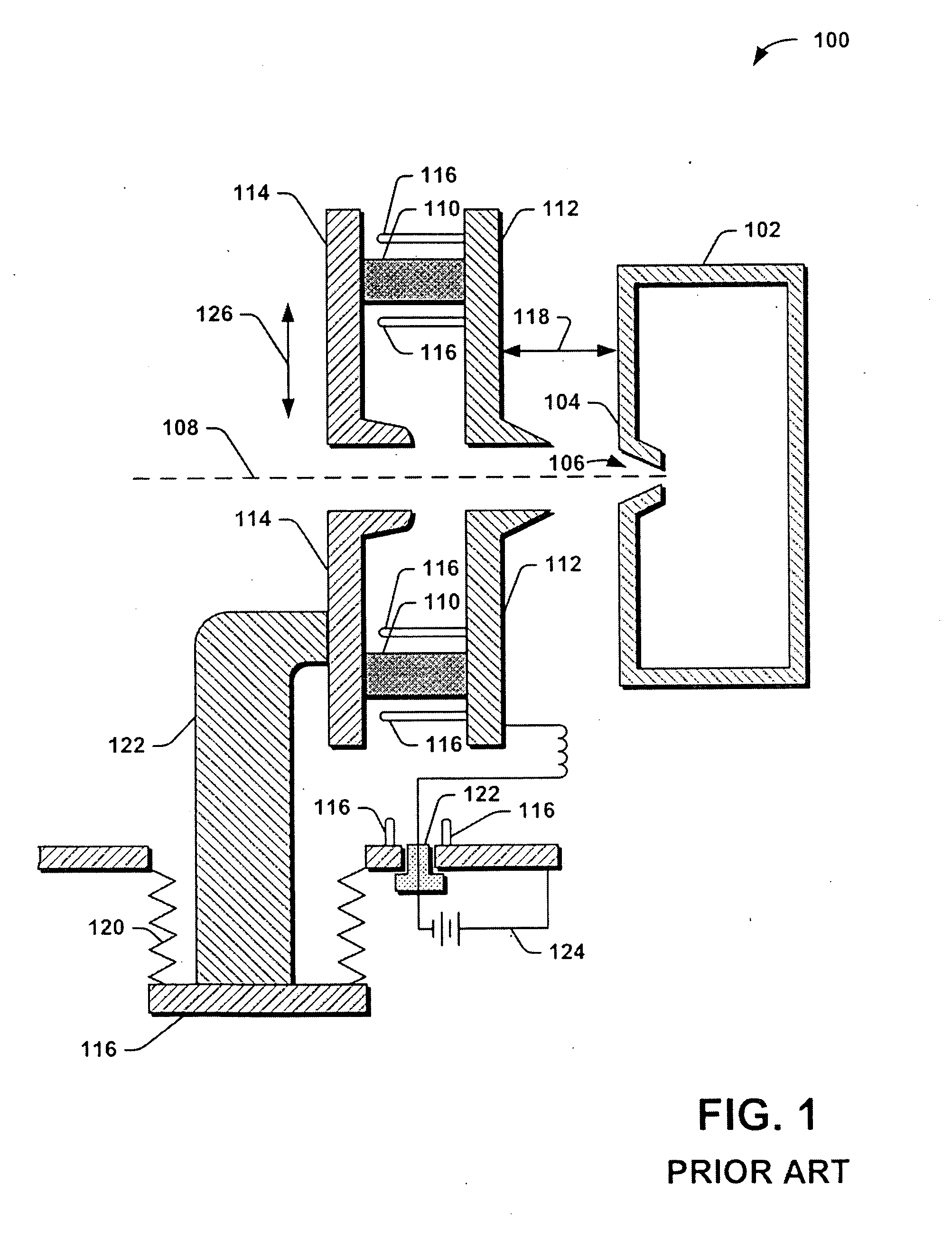
Adding to all these deleterious environment factors, another fact is that the electrodes (e.g., suppression and ground electrodes) may have to be mechanically manipulated in position relative to the ion source, making the situation even more complicated.
This arrangement not only requires a flexible wire or spring to connect the suppression feed through to the electrode, but also, the feed through itself is vulnerable to all the problems mentioned supra.

Method used


Image

  • Extraction electrode manipulator
  • Extraction electrode manipulator
  • Extraction electrode manipulator

Examples


Embodiment Construction

[0018]The present invention is directed generally towards an improved extraction manipulator system and method used in an ion implantation system that utilizes an isolated insulation standoff. More particularly, the system and method efficiently extract an ion beam utilized in the ion implantation system with less frequent maintenance of the insulating standoff. Accordingly, the present invention will now be described with reference to the drawings, wherein like reference numerals are used to refer to like elements throughout. It should be understood that the description of these aspects are merely illustrative and that they should not be taken in a limiting sense. In the following description, for purposes of explanation, numerous specific details are set forth in order to provide a thorough understanding of the present invention. It will be evident to one skilled in the art, however, that the present invention may be practiced without these specific details.

[0019]Turning now to FI...


PUM


Abstract

An extraction electrode manipulator system, comprising an ion source, a suppression electrode and a ground electrode, wherein the two electrode are supported by coaxially arranged two water cooled support tubes. A high voltage insulator ring is located on the other end of the coaxial support tube system to act as a mechanical support of the inner tube and also as a high voltage vacuum feedthrough to prevent sputtering and coating of the insulating surface.

Description

FIELD OF THE INVENTION[0001]The present invention relates generally to ion implantation systems and more specifically to a system for utilizing an extraction electrode manipulator that reduces the amount of maintenance required for the insulators within the manipulator.BACKGROUND OF THE INVENTION[0002]In the manufacture of semiconductor devices and other ion related products, ion implantation systems are used to impart dopant elements into semiconductor wafers, display panels, or other types of workpieces. Typical ion implantation systems or ion implanters impact a workpiece with an ion beam utilizing a known recipe or process in order to produce n-type or p-type doped regions, or to form passivation layers in the workpiece. When used for doping semiconductors, the ion implantation system injects selected ion species to produce the desired extrinsic material. Typically, dopant atoms or molecules are ionized and isolated, sometimes accelerated or decelerated, formed into a beam, and ...

Claims


Application Information

Patent Timeline
IPC IPC(8): H01J37/08H01J27/00
CPCH01J27/024H01J37/023H01J37/04H01J37/067H01J37/08H01J37/15H01J2237/31701H01J2237/002H01J2237/0213H01J2237/0458H01J2237/08H01J2237/083H01J37/3171
Inventor SATOH, SHUADAMIK, JOHNSIERADZKI, MANNY
Owner AXCELIS TECHNOLOGIES
Learn More