Eureka AIR delivers breakthrough ideas for toughest innovation challenges, trusted by R&D personnel around the world.

Remotely controlled fire protection system

a fire protection system and remote control technology, applied in the direction of flow control using electric means, ratio control, instruments, etc., can solve the problems of reducing effectiveness, many buildings being threatened, and reducing so as to maximize the amount of water hitting, increase the effectiveness of fire protection systems, and comprehensive and accurate fire fighting strategies

Inactive Publication Date: 2010-03-18
MORGENSTERN PAUL +2
View PDF59 Cites 66 Cited by
  • Summary
  • Abstract
  • Description
  • Claims
  • Application Information

AI Technical Summary

Benefits of technology

[0019]When activated the central processor turns on in sequence various valves and nozzles wetting down the roof and surrounding areas of the property. The valves and nozzles may be wired or wireless devices. The system may utilize existing irrigation systems. By activating the sections of the existing irrigation the effectiveness of the fire protection system will be increased as well as keeping landscaping watered during periods of evacuation when power is not typically available and standard irrigation systems will not operate. The system may also utilize water nozzles and / or watering devices not used during standard landscape irrigation that are strategically placed to wet down sources of fire fuel near the structure such as trees, bushes and scrub brush to prevent these sources of fire fuel from igniting.
[0020]When activated the central processor communicates back to the fire authority that the fire protection system has been successfully activated. The central processor transmits back information such as but not limited to water flow, water pressure, air temperature, roof temperature, wind speed, wind direction, humidity, still, live, infrared or thermal images of the protected property. This valuable information can assist the fire authority in creating a more comprehensive and accurate fire fighting strategy.
[0021]When activated, based on inputs from sensors such as but not limited to water pressure, air temperature, roof temperature, wind speed, wind direction and direction of approaching fire, the central processor can adjust the water soaking strategy to maximize the amount of water hitting its target and minimizing unnecessary water wasted.

Problems solved by technology

There are minimal ways to protect buildings and or property from wildfires.
In addition there may be many buildings threatened in a wildfire situation.
Fire retardants have to be repeatedly applied to the property each fire season and have reduced effectiveness after rains wash them away or heavy winds blow them away.
Additionally, there is a negative environmental impact from surrounding homes and businesses with the chemicals found in fire retardants.
There is currently no method available for a fire authority to remotely mitigate potential exterior structure fires resulting from wide spread wild fires, proximal structure fires or proximal brush fires.
There is no currently viable method available for fire authorities to determine if any existing fire protection system have been activated.
There are no current viable systems that give the fire control authority a method to remotely turn off a fire suppression system that was activated autonomously or remotely.
There are no current viable systems that can detect water pressure so as to active and deactivate fire protection systems or adjust which zones are active within the systems in order to maintain a desired water pressure within the area.
There are no existing systems that act as a peer-to-peer mesh network to continue to autonomously communicate directly with other proximal fire suppression systems to share current environmental and fire threat data without the communication first being routed through a central control authority when communication to the central control authority is cut off.
There are no existing solutions that are alerted when communication to a remotely controlled fire protection system has failed.
There are no existing solutions that have the ability to adjust the roof or property wetting strategy based on current environmental and fire conditions such as wind speeds, wind direction and / or temperature by changing the wetting methodology or adjusting which sprinklers are active and the duration they are active in order to maximize the water concentration in the most effective location by minimizing the amount of water blown away due to high wind common during wild fires.
There are no current solutions that can automatically or manually adjust the roof or property wetting strategy to concentrate water in areas of higher combustion risk or areas determined by sensors to have higher temperature concentrations relative to surrounding areas, potentially caused by a burning ember.
The method is insufficient in that a remote method of activation is not described.
This method does not relay information back to the fire authority, in addition the fire authority may need to remotely activate and deactivate the system to maintain water pressure in a given area.
The method is insufficient in that a remote method of activation is not described.
This method does not relay information back to the fire authority, in addition the fire authority may need to remotely activate and deactivate the system to maintain water pressure in a given area.
This method is insufficient since it releases the fire suppressant only when the container is exposed to extreme heat rather than being remotely activated to release the fire suppressant into the water lines.
This method is insufficient as it does not contain a remote triggering activation feature and it only focuses on built-in sprinkler systems rather than exterior mounted sprinklers.

Method used


Image

  • Remotely controlled fire protection system
  • Remotely controlled fire protection system

Examples


Embodiment Construction

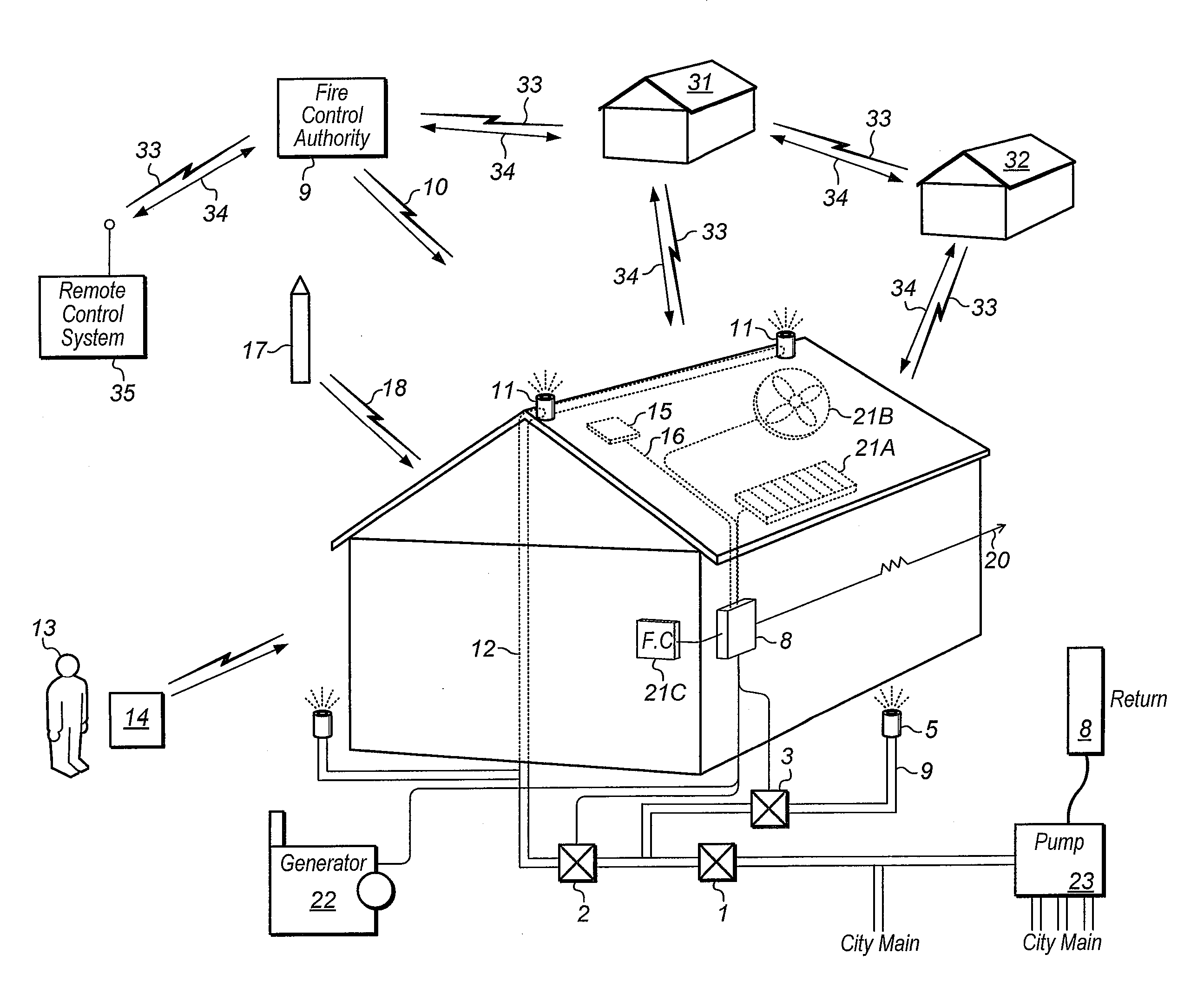
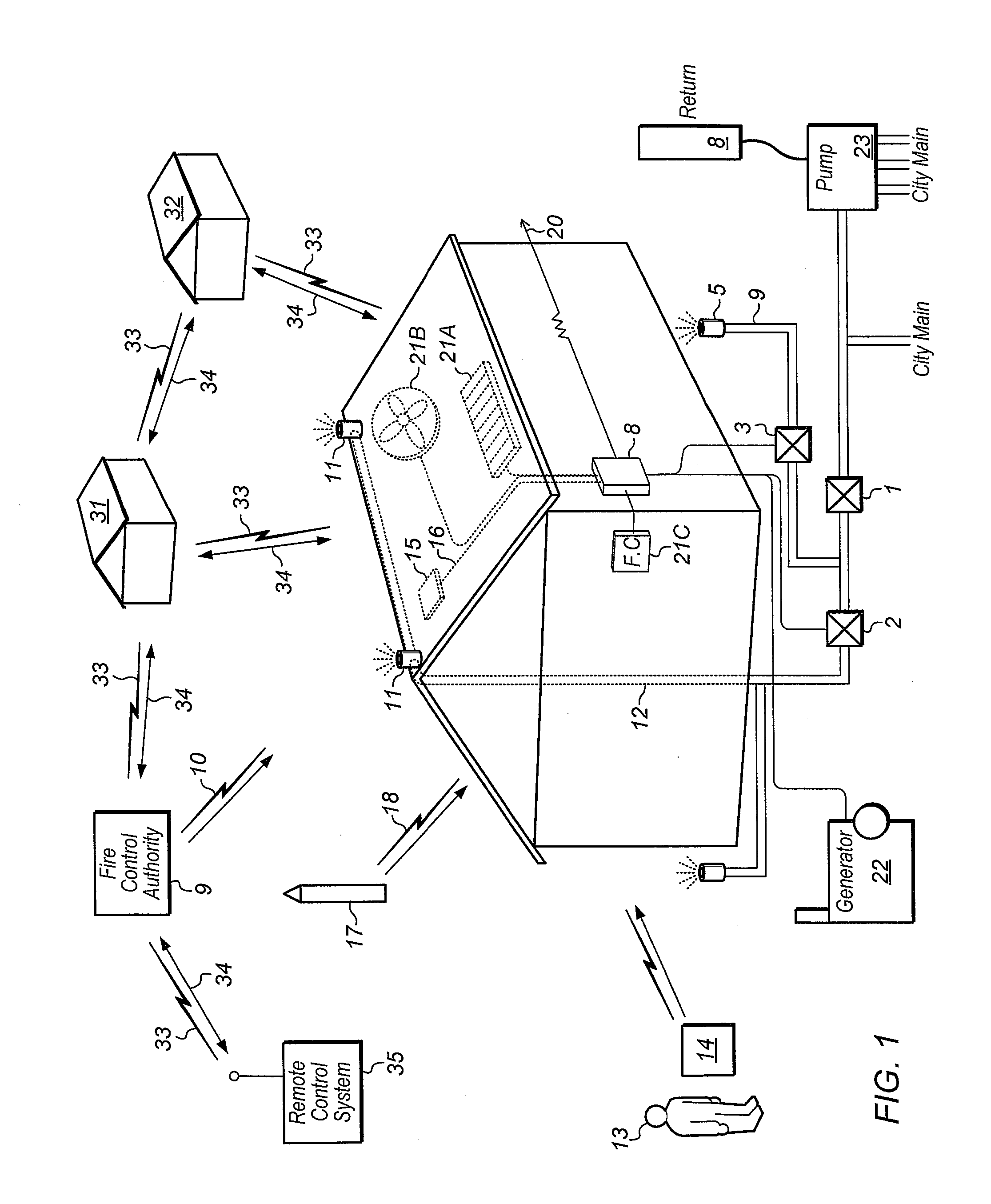
[0033]With reference now to FIG. 1, a new fire protection system for buildings using remote control embodying the principals and concepts of the present invention and generally designated by the reference numeral 8 will be described.

[0034]As best illustrated in FIG. 1, fire control system 8 generally includes a building with at least one water or misting nozzle 11 mounted on the house or in the ground spraying the side and roof of the structure, supplied with water via piping 12 controlled by manual valve 1 further controlled by water valve 2. In one embodiment Water valve 2 is controlled via wireless connection to the fire control system 8. In another embodiment water valve 2 is connected to the fire control system 8 with a wire or cable 6. Water valve 3 controlled by fire control system 8 allows water to flow via piping 4 to sprinkler nozzle 5. In one embodiment fire control system 8 is activated by heat sensor 15 via a wire or cable 16.

[0035]In one embodiment perimeter sensor 17 ...


PUM


Abstract

Method and apparatus for remotely controlling a fire protection system for buildings. This method of fire protection uses a wireless or wired control system to remotely activate a fire protection system by sending it an activation signal or activation message wherein one or more commands can configure the system with specified operation instructions. The system utilizes roof top sprinklers and may additionally utilize existing irrigation systems or additional zones only used during the prevention of wildfires to wet down area in advance of fires. The system can be controlled by various municipal fire authorities that are given the authority to control fires. Immediate control of the system is always available to the transmitting authority. When activated, the central processor communicates to the authority that activated the fire protection system. The central processor transmits information back to the transmitting authority such as but not limited to water flow confirmation, water pressure, air temperature, roof temperature, wind direction, humidity and still or live images of the protected property.

Description

PRIORITY CLAIM[0001]This application claims the benefit of priority of U.S. Provisional Patent Application Ser. No. 61 / 098,230 entitled “REMOTELY CONTROLLED FIRE PROTECTION SYSTEM”, filed on Sep. 18, 2008, whose inventors are Paul Morgenstern, Robbie Clark and James Jolly Clark, which is hereby incorporated by reference in its entirety as though fully and completely set forth herein.BACKGROUND OF THE INVENTION[0002]1. Field of the Invention[0003]The invention generally relates to a method and apparatus for remotely controlling fire protection systems.[0004]2. Description of the Relevant Art[0005]There are minimal ways to protect buildings and or property from wildfires. The only methods available up to this time have been the fire department or the use of fire retardants around the property. The fire department must be on site to protect the building. In addition there may be many buildings threatened in a wildfire situation. Fire retardants have to be repeatedly applied to the prop...

Claims


Application Information

Patent Timeline
IPC IPC(8): G05D7/06
CPCA62C37/40A62C35/64
Inventor MORGENSTERN, PAULCLARK, ROBBIECLARK, JAMES JOLLY
Owner MORGENSTERN PAUL
Why Eureka
Eureka Blog
Learn More