Plug-in sensor having improved fluid mechanics

Active Publication Date: 2010-03-18
ROBERT BOSCH GMBH
View PDF16 Cites 23 Cited by
  • Summary
  • Abstract
  • Description
  • Claims
  • Application Information

AI Technical Summary

Benefits of technology

[0010]Therefore, a plug-in sensor for determining at least one parameter of a fluid medium streaming in a main flow direction is provided, which avoids the afore-described disadvantages of known constructions either entirely or partially. The fluid medium may be a fluid or a gas, and the at least one parameter may be, for example, a pressure, a temperature, a velocity, or an air-mass throughput or the like. Especially preferred is the development of the plug-in sensor as hot-film air mass sensor for measuring an aspirated air mass of an internal combustion engine, the air mass flowing through a flow pipe.
[0013]The special feature of the provided plug-in sensor is that the plug part at least partially has an airfoil profile which is designed in such a way that an asymmetrical flow of the fluid medium comes about when the plug is introduced into the flowing fluid medium. It is basically possible to use different developments of airfoil profiles, which are known from the airplane construction, for instance. The advantage of the design according to the present invention is that the use of the asymmetry effects makes it possible to selectively increase flow velocities on one side of the plug part and to reduce them on the other side. In this way increases in the velocity of the streaming fluid medium are able to be brought about where this is especially advantageous for the operation of the plug-in sensor. As is the case in one preferred development of the present invention, for instance, the at least one outlet opening (i.e., one or all outlet openings of the at least one outlet opening) may be disposed laterally on the at least one airfoil profile. The airfoil profile preferably has an outlet side with at least one outlet opening, and an opposite side without outlet opening. In this case the airfoil profile is preferably designed in such a way that, when the plug part is introduced into the streaming fluid media, a flow profile in the fluid media comes about in which the velocity of the streaming fluid media is higher on the outlet side than on the opposite side. Because of this increase in the flow velocity in the region of the at least one outlet opening, the throughput through the at least one flow channel is able to be increased and the functionality of the plug-in sensor is improved as a result due to the hydrodynamic suction effect.
[0019]One idea according to the present invention, as an alternative or in addition to utilizing the asymmetrical flow profile in order to increase the throughput rate through the at least one flow channel, consists of providing a separation element on one side of the airfoil profile (preferably on precisely one side), which likewise provides an asymmetrical flow but which contributes to a stabilization of the flow separation from the plug part. This stabilization is implemented in such a way that the separation always takes place in a specified separation region on the airfoil profile without greater fluctuations or oscillations. For this purpose, the at least one separation element is preferably designed such that an at least local pressure minimum is induced on this side of the airfoil profile when the plug part is introduced into the streaming fluid medium. The more pronounced this fixed pressure minimum and the subsequent pressure increase, the more stable the separation of the streaming fluid medium from the plug part in this separation region.
[0021]A further alternative or additional option for designing the separation element consists of providing a stepped profile. A stepped profile is to be understood as a step in the airfoil profile, i.e., expressed in lay terms, first a “bent in one direction” and then “a bent in the opposite direction”.Preferably, in particular due to the simplified construction, this stepped profile has a rectangular shape. Other stepped profiles are also conceivable, however, such as ones having projecting, sharply pointed steps, in order to induce an even more reliable separation of flow boundary layers in this region.
[0023]The two afore-described effects, i.e., facilitating the fluid throughput through the at least one flow channel by an asymmetrical flow profile, and the fixation of the separation region are able to be advantageously combined in that at least one of the at least one outlet openings is disposed in the region of the at least local pressure minimum. In particular at least one bypass opening may be disposed entirely or partially in the region of the at least one separation element and / or downstream from the at least one separation element. Such a placement of the at least one main flow outlet opening is also advantageous as an alternative or in addition. This special design of the set-up of the at least one outlet opening combines the two afore-described effects of the present invention in an especially advantageous manner. The exiting of air from the at least one outlet opening otherwise causes interruptions in the flow of the medium at just about every other location at the plug-in sensor. These interruptions are lowest in the region of the flow separation, which constitutes a further positive side effect of this placement.

Problems solved by technology

One problem with such a type of sensor known from published German patent document DE 101 11 840, for instance, is that contamination of the sensor element may frequently occur, such as contamination by water, oil or other fluids, or other types of soiling.
This soiling deposit can lead to an undesired effect on the measuring signal of the sensor, especially because a fluid film on the surface of the sensor affects the thermal conductivity of the surface, which results in a falsification of the measuring signals.
Similar problems occur not only in hot-film air mass meters, but in other types of sensors as well, which are used for measuring fluid parameters in a fluid flow.
However, in the plug-in sensor constructions described in the related art it is disadvantageous that the plug-in sensors described, because of their aerodynamically disadvantageous shape often cause problems in the intake tract with regard to a loss in pressure attributable to flow resistance.
In addition, the signal reproducibility of the signals from such sensors is comparatively low.
One disadvantage is, for instance, that the flow-diversion part is normally fixedly installed in a section of the flow pipe.
This fixed installation entails additional costs in the manufacture of this pipe section, just as does the provision of the additional flow-conducting wall.
Furthermore, in the development as one piece the installation length is also too long for many applications.

Method used


Image

  • Plug-in sensor having improved fluid mechanics
  • Plug-in sensor having improved fluid mechanics
  • Plug-in sensor having improved fluid mechanics

Examples


Embodiment Construction

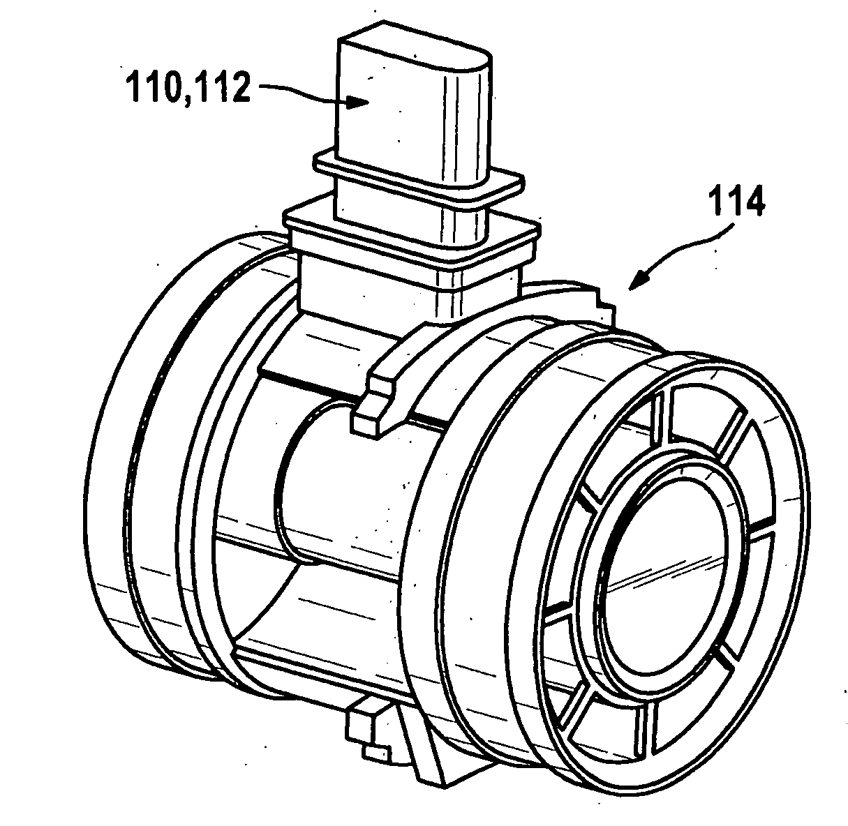
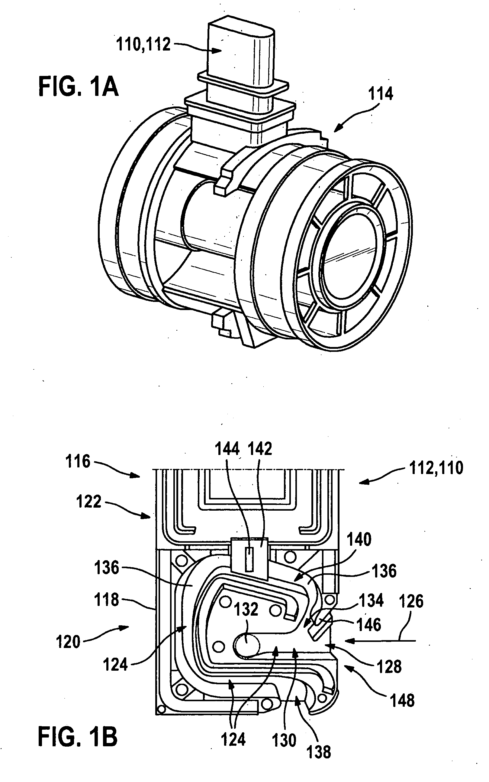
[0034]FIG. 1A shows an exemplary embodiment of a plug-in sensor 110, which corresponds to the related art and, in this case, is developed as a hot-film air mass meter 112. Hot-film air mass meter 112 is installed in an intake tract 114 of an internal combustion engine, which is not shown in FIG. 1A. Such hot-film air mass meters 112 are commercially available. Hot-film air mass meter 112 is designed to detect the flow direction of an aspirated flow and is developed to record the load in internal combustion engines having gasoline or Diesel fuel injection. The hot-film air mass meter 112 is usually installed between an air filter and a throttling device, and it is usually installed as a preassembled module. Accordingly, plug-in sensor 110 has a plug part 116, which is shown in FIG. 1B in an opened state in a side view, and which projects into intake tract 114 in FIG. 1A. It can be seen in FIG. 1B that, in this exemplary embodiment of hot-film air mass meter 112, a measuring housing 1...


PUM


Abstract

A plug-in sensor for determining an aspirated air mass of an internal combustion engine flowing through a flow pipe has a plug part, which is able to be introduced into the streaming medium with a specified orientation to the main flow direction. Provided in this plug part is at least one flow channel having at least one inlet opening and at least one outlet opening. Accommodated in the at least one flow channel is at least one sensor for determining the at least one parameter. The plug part has a rounded inflow side, which points counter to the main flow direction. The plug part at least partially has an airfoil profile, which is designed such that an asymmetrical flow profile of the fluid medium comes about when the plug part is introduced into the streaming fluid medium.

Description

BACKGROUND OF THE INVENTION[0001]1. Field of the Invention[0002]The present invention is based on devices for measuring at least one parameter of a streaming fluid medium, in particular a fluid medium streaming through a flow pipe, as it is known in various fields of technology.[0003]2. Description of Related Art[0004]In many processes such as, for instance, in the field of industrial processing engineering, chemistry or machine construction, fluid media, especially masses of gas (e.g. an air mass) having particular properties (such as temperature, pressure, flow velocity, mass flow, etc.) have to be supplied in a defined manner. Among these are combustion processes, in particular, which run under regulated conditions.[0005]An important application example is the combustion of fuel in internal combustion engines of motor vehicles, especially ones having subsequent catalytic exhaust gas purification, in which a certain air mass has to be supplied per unit time in a controlled manner ...

Claims


Application Information

Patent Timeline
IPC IPC(8): G01F1/684
CPCG01F1/6842G01F1/684G01F1/692G01F1/34
Inventor MAIS, TORSTENKONZELMANN, UWEGMELIN, CHRISTOPH
Owner ROBERT BOSCH GMBH
Why Eureka
Try Eureka