Carton feeder device and method for feeding a carton to a conveyor track

Active Publication Date: 2013-05-16
NORDEN MASCH AB
View PDF16 Cites 11 Cited by
  • Summary
  • Abstract
  • Description
  • Claims
  • Application Information

AI Technical Summary

Benefits of technology

The patent describes a carton feeding device that can insert cartons into a moving conveyor track with parallel teeth. The cartons are held in a rhombic shape, which reduces the horizontal extension of the cartons during the insertion and allows for some space between the cartons and the teeth. This allows for the insertion of cartons into the holding space with the same width as the carton itself. The device can be mounted along the conveyor track, allowing for an increased throughput rate of the feeding system. The angle between the upper wall and one of the side walls of the carton is preferably between 50 and 80 degrees, and the cartons are pre-tensioned towards a rectangular shape. The device includes a holding protrusion and a hold down element to stop the carton from escaping the conveyor track. The technical effects of the invention include increased efficiency in carton feeding and insertion, reduced space requirement, and increased capacity of the feeding system.

Problems solved by technology

Such a solution is often difficult to achieve since it may involve a redesign of the machine and at some point, it is not possible to reduce the cycle time for a specific operation.
Such a solution requires more space and is not as cost-effective, but may be a possibility when an older production line is to be upgrades.
There are several problems associated with this solution.
One problem is that the carton is driven into the leading flight and is pulled against the leading flight during the opening of the carton.
This will put a great deal of strain on the carton, which may lead to damages to the outer surfaces of the carton.
Since the distance over which the carton is opened is relatively short, the strain on the carton is further increased.
A further disadvantage may be to handle cartons in which residual glue inside the carton causes the sides of the carton to stick to each other.
Such a carton may be further damaged during the opening and may also disrupt the insertion of further cartons.
These solutions may work well for some applications, but may be inflexible, especially when the throughput of the system is to be increased.

Method used


Image

  • Carton feeder device and method for feeding a carton to a conveyor track
  • Carton feeder device and method for feeding a carton to a conveyor track
  • Carton feeder device and method for feeding a carton to a conveyor track

Examples


first embodiment

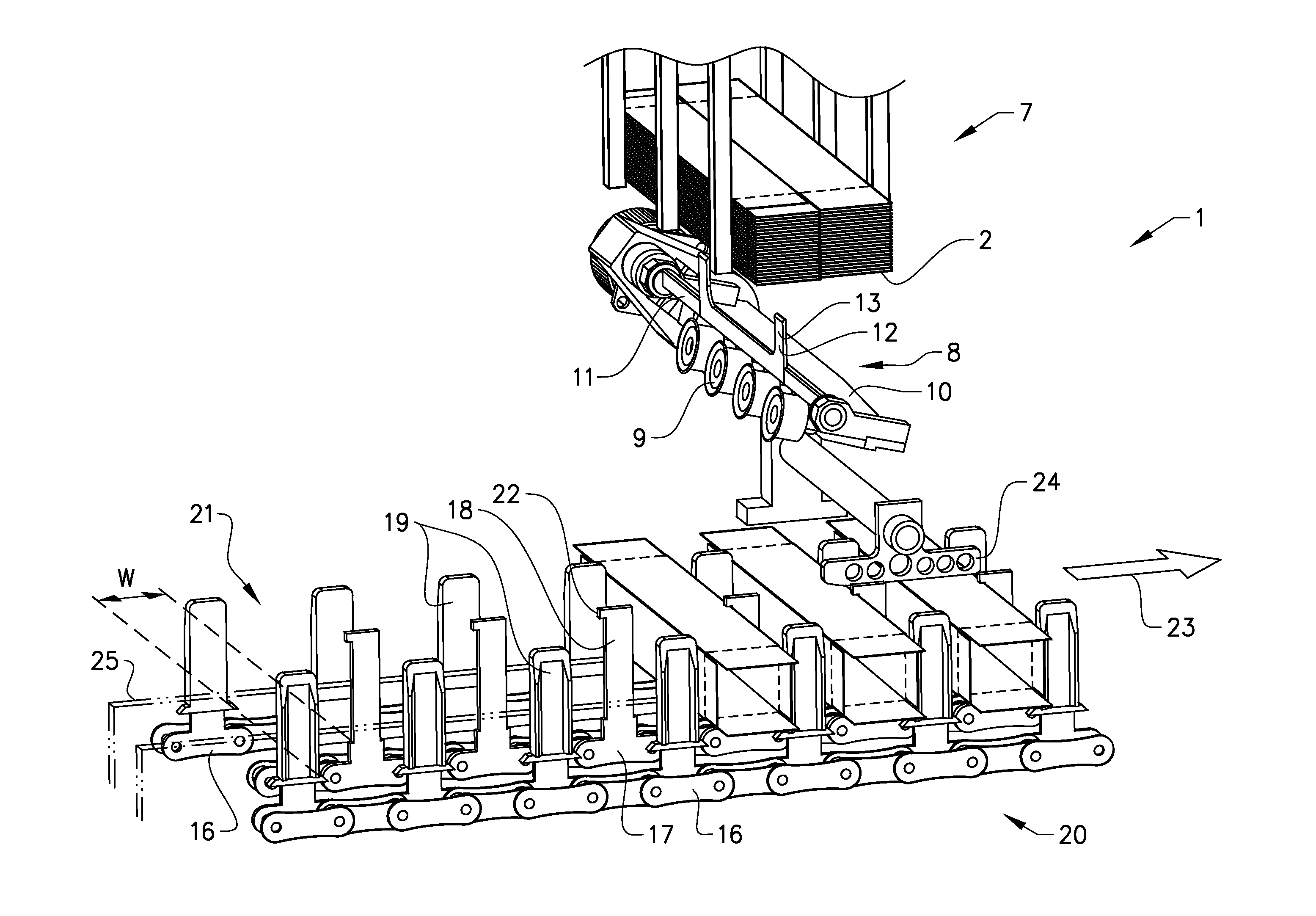
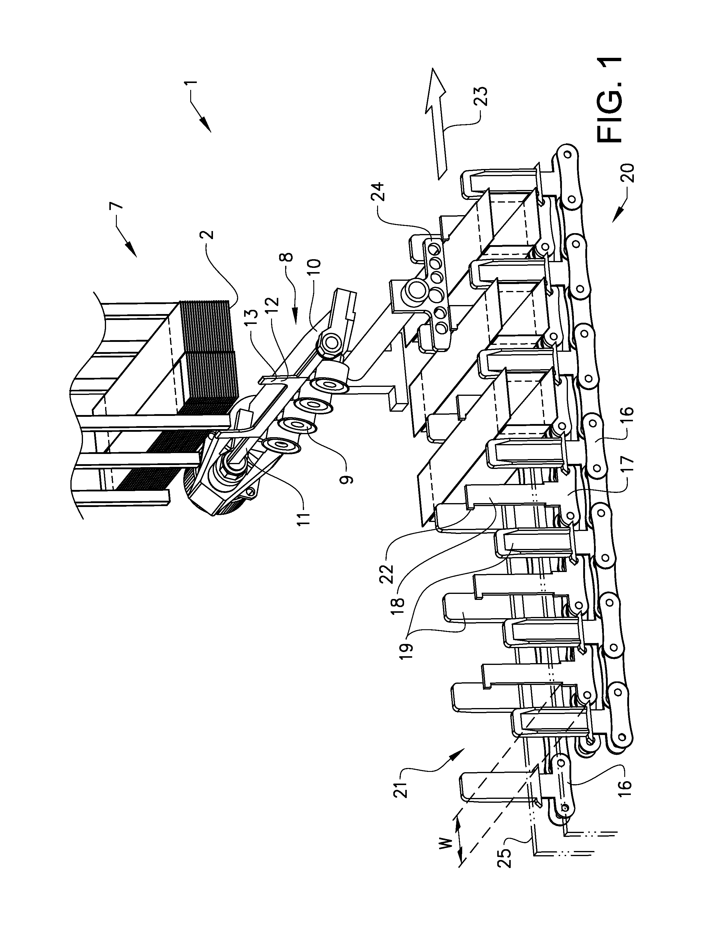
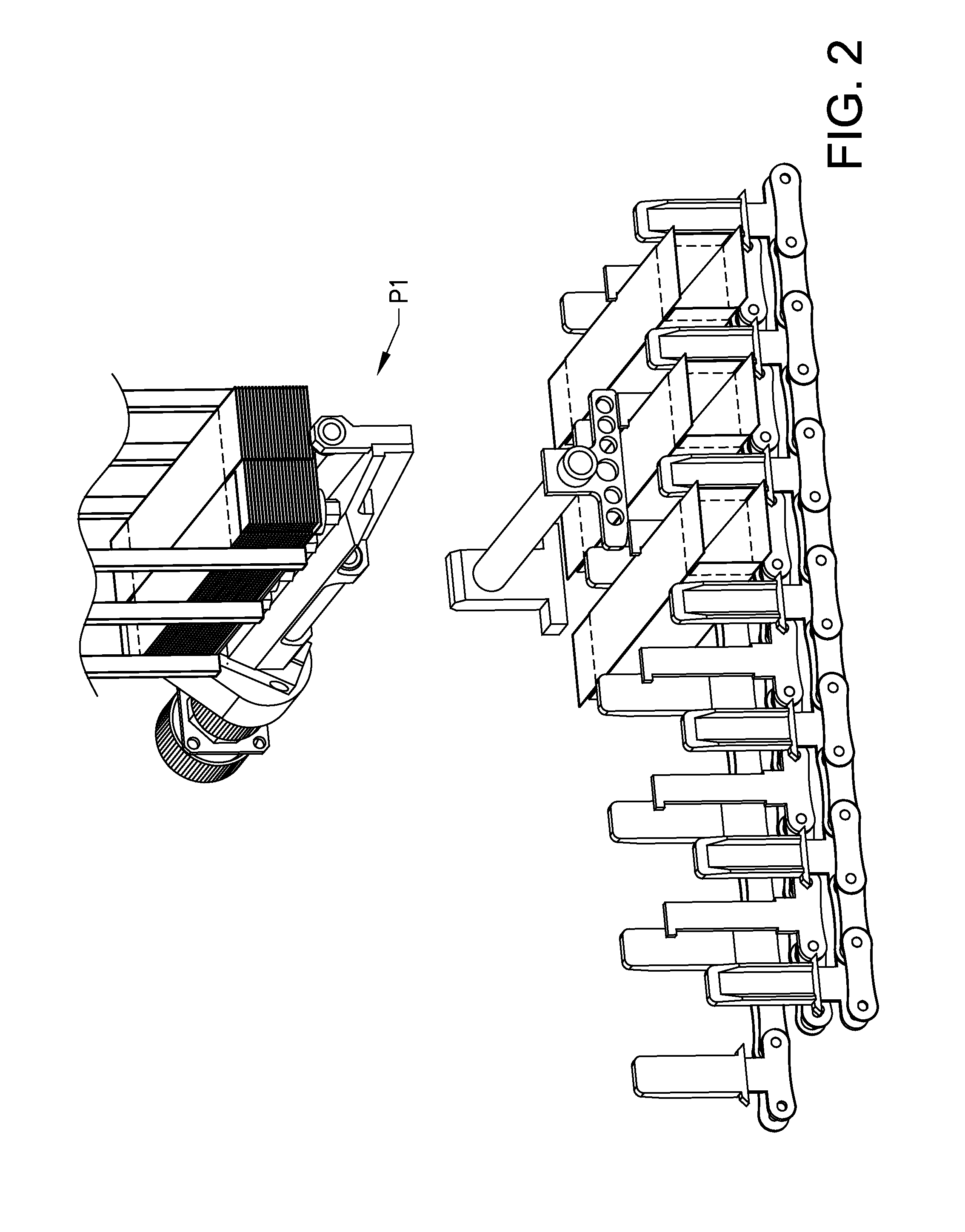
[0029]FIGS. 1 to 6 shows a carton feeding device 1 adapted to pick-up carton blanks from a magazine, to open them and to subsequently feed them to a conveyor track. The carton blanks are flat-folded, pre-glued cartons 2 comprising four sides and having closure flaps at their end regions. When a carton blank is erected or opened, a rectangular box body is obtained, into which an object such as a tube or bottle is to be inserted, before the box is closed and / or sealed. The sides of the carton 2 will in this description be referred to as the upper wall 3, the lower wall 4, the front wall 5 and the rear wall 6. These references indicate the directions of the sides of a carton being conveyed in the conveyor track, with reference to the moving direction of the conveyor track. The carton blanks are fed from a magazine 7. In this example, the magazine is vertically disposed such that the carton blanks are removed downwards from the magazine, but other positions and angles are also possible....

second embodiment

[0048]In the inventive carton feeding device, the erecting fingers will erect the carton blanks by an angle of less than 90 degrees. In this embodiment, a carton is not opened completely before it is inserted into the holding space of the conveyor track. The angle α between the plane of the vacuum cups and the bearing surface of the erecting fingers is in this embodiment between 100 and 140 degrees, and is preferably around 120 degrees. In this embodiment, the hold down element 24 is essential, since the pre-tension in the carton will be in the direction to return the partly opened carton to the carton blank state, i.e. to retract. Protrusions 22 on the teeth may also be provided in this embodiment in order to hold the carton in position.


PUM


Abstract

Embodiments include a carton feeding device for feeding cartons to a conveyor track, comprising a pick-up head with a plurality of vacuum cups, an erecting finger pivotally suspended at the pick-up head, where the pick-up head has a pick-up position (P1) and an insertion position (P2), where the carton is held with an angle α between the holding plane of the pick-up head and the bearing surface of the erecting finger, wherein the angle α differs from 90 degrees with at least 10 degrees in the insertion position (P2), where the carton is inserted between two parallel teeth of the conveyor track, and where the distance between the teeth is substantially equal to the width of the upper wall of the carton.

Description

TECHNICAL FIELD[0001]The present invention relates to a carton feeder device for a conveyor track.BACKGROUND ART[0002]In the industry concerned with packing smaller objects such as tubes, bottles and the like in carton boxes, there is a constant need to increase the productivity of the packing machines. One aspect of a packing machine is the number of units that the machine can handle during a specific time interval. There are different ways of achieving a higher throughput in such a machine. One way is to reduce the cycle time for each object, i.e. to allow more objects to pass the machine during the same time interval. Such a solution is often difficult to achieve since it may involve a redesign of the machine and at some point, it is not possible to reduce the cycle time for a specific operation. Another way to increase the throughput in a production line is to use several parallel machines, at least for some operations. Such a solution requires more space and is not as cost-effe...

Claims


Application Information

Patent Timeline
IPC IPC(8): B65G47/04
CPCB31B2201/284B31B2201/286B31B2201/289B65G47/04B65B43/265B65B43/305B65B43/325B31B2203/003B31B50/786B31B50/788B31B50/804B31B2100/00B31B2120/30B31B50/80
Inventor LUNDGREN, CHRISTERNILSSON, JAN
Owner NORDEN MASCH AB
Why Eureka
Try Eureka