
Motion control sensor system for a moving unit and motion control system

Inactive Publication Date: 2010-03-11
HITACHI CABLE
View PDF16 Cites 5 Cited by
  • Summary
  • Abstract
  • Description
  • Claims
  • Application Information

AI Technical Summary

Benefits of technology

[0025]Particularly, since the effect of temperature generated by a brake on sensors is reduced, a service temperature range characteristic of the sensors environment of use can be narrowed and thereby it becomes easily possible to increase the precision of the sensors and reduce their costs.
[0038](4) Since a plurality of physical quantity sensors for detecting physical quantities are used in combination, the cost and weight of the entire vehicle control system are reduced and materials used in the system and assembling costs are also reduced.

Problems solved by technology

Accordingly the sensors are not contributing to an accurate control.
In this method, however, since the tires to which the sensors are attached are rotated to run the vehicle, power supply to the rotating parts and wireless information transmission from the rotating parts are needed, making the system very complex.
Another problem is that the information transmission may be discontinued.
When the brake is applied, portions at which the strain sensors are attached become hot due to heat generated by the brake.
Accordingly, changes in temperature make it difficult to perform precise measurements and various devices are required to obtain reliable measurement precision, resulting in an expensive method.
This method requires a high cost because four displacement sensor units are needed.
However, signals detected are delayed with respect to a response from the road surface, so the response time has been required to be further reduced.
In a system in which strain sensors are used, a plurality of sensors must be attached to correct the sensitivity of other axes, increasing the cost.

Method used


Image

  • Motion control sensor system for a moving unit and motion control system
  • Motion control sensor system for a moving unit and motion control system
  • Motion control sensor system for a moving unit and motion control system

Examples


first embodiment

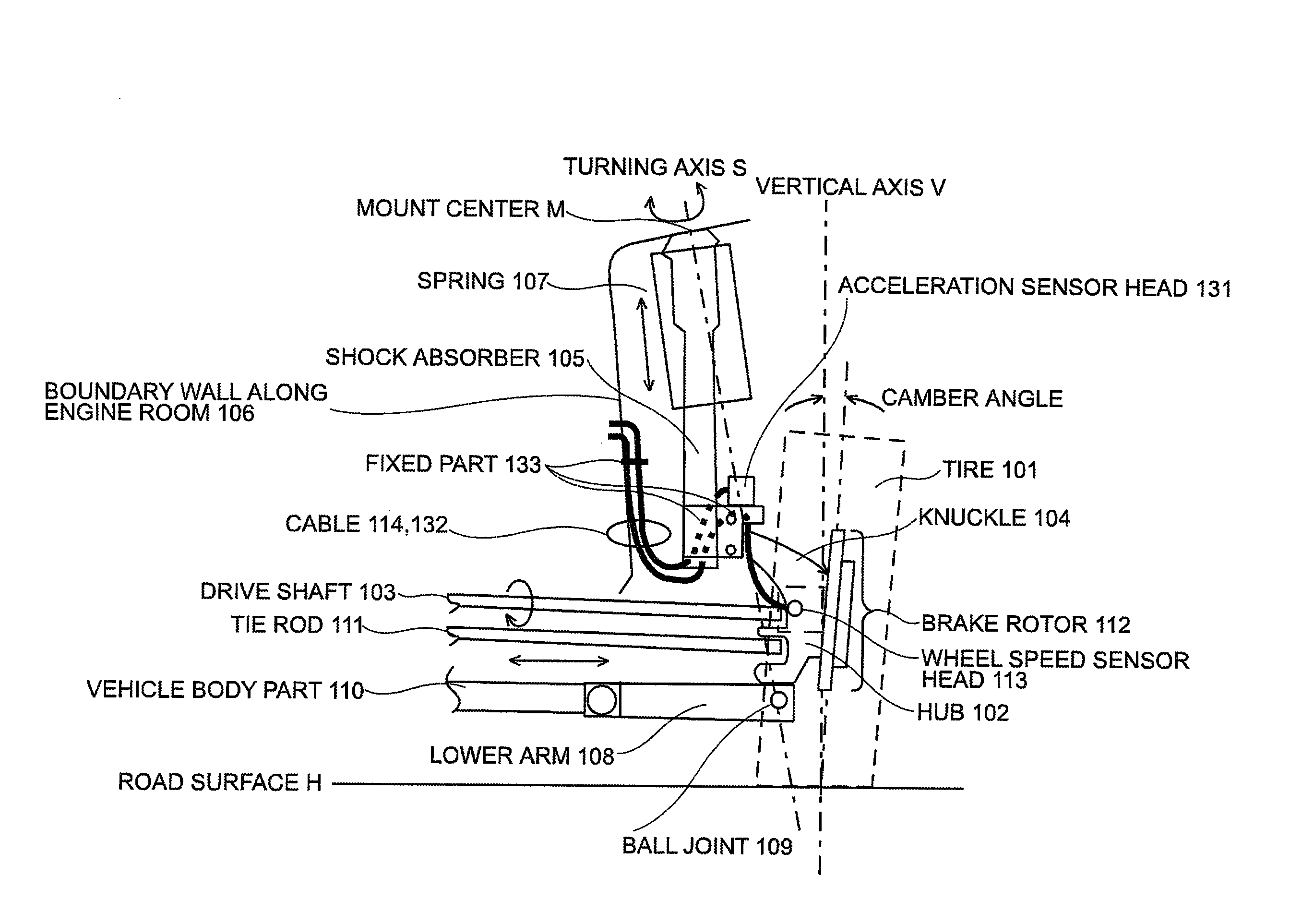
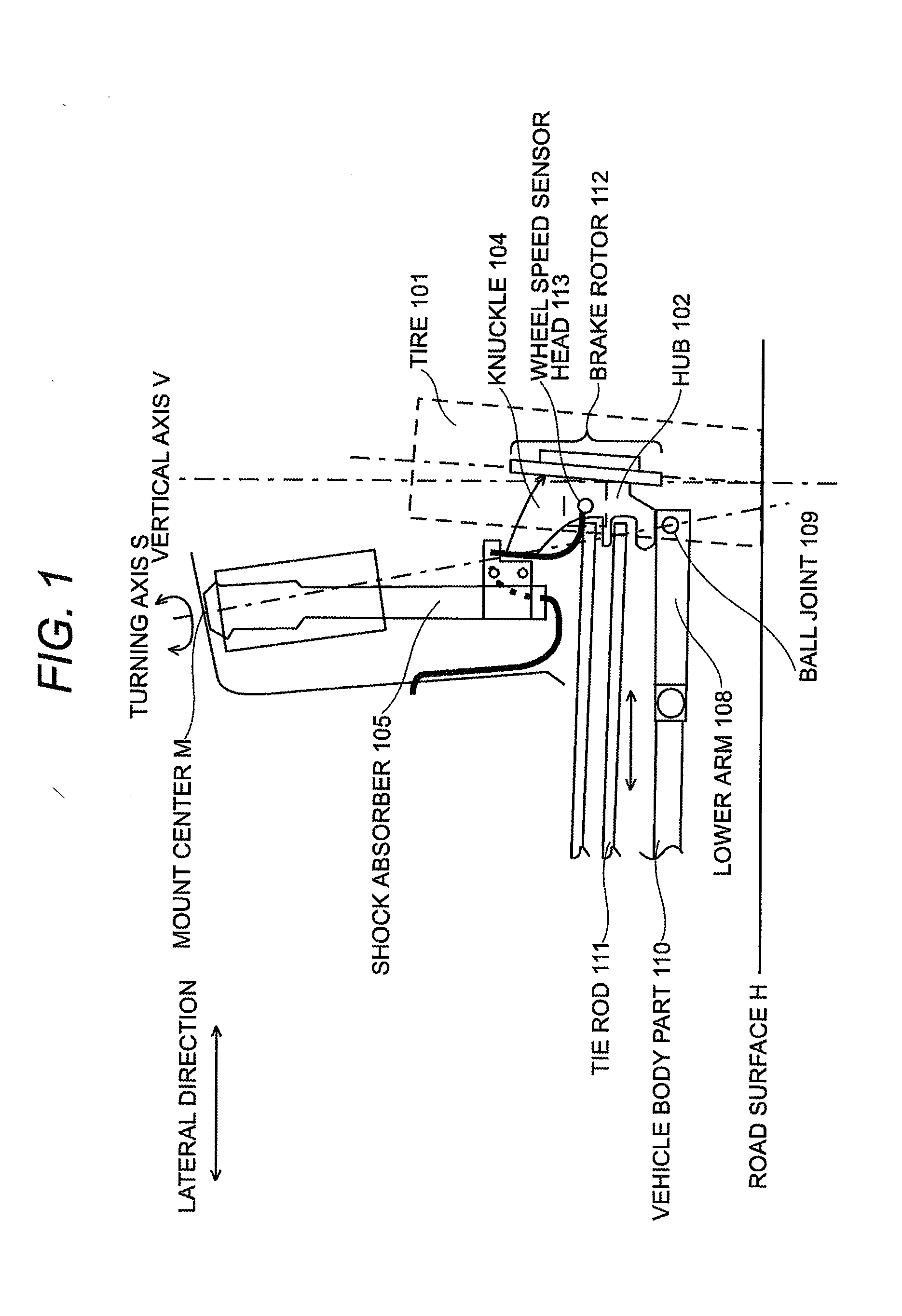
[0091]FIG. 5 shows a motion control system according to the present invention, which an acceleration sensor is attached to the right front wheel of a front-wheel-drive vehicle. An acceleration sensor head 131 including an acceleration sensor for detecting lateral acceleration is attached to the lower part (below the spring 107) of the shock absorber 105 with a bracket or the like at a position where the detection axis of the acceleration sensor crosses the turning axis S. A cable 132 connected to the acceleration sensor head 131 is fixed at a cable securing part 133 (the lower part of the shock absorber 105), fixed at another cable securing part 133 (the boundary wall 106 along the engine room) with a sag, and connected to an acceleration signal processing circuit (not shown) in the engine room. In this embodiment, the cable 114 connected to the wheel speed sensor is also fixed together at the two cable securing parts 133 at which the cable 132 is fixed.

[0092]The acceleration sensor...

fourth embodiment

[0101]FIG. 8 shows the present invention. In this embodiment, the acceleration sensor head 131 is attached to the securing part at which the wheel speed sensor cable is fixed. In this placement, the member for fixing the acceleration sensor can also be used to fix the wheel speed sensor cable together, reducing the member cost, member weight, and assembling man-hours.

fifth embodiment

[0102]FIGS. 9 and 10 show the present invention. In this embodiment, the first acceleration sensor head 131, second acceleration sensor head 141, and wheel speed sensor head 113 are interconnected with a signal submitting cable 171. Suppose that the number of conductors used by the wheel speed sensor is N0, the number of conductors used by the first acceleration sensor is N1, and the number of conductors used by the second acceleration sensor is N2. Then, the number of conductors of a cable for interconnecting the wheel speed sensor head 113 and first acceleration sensor head 131 is N0, the number of conductors of a cable for interconnecting the first acceleration sensor head 131 and second acceleration sensor head 141 is N0+N1, and the number of conductors of a cable for connecting the second acceleration sensor head 141 to an electric circuit in the engine room is N0+N1+N2. An intermediate sensor head is used to relay conductors used by a sensor head upstream of the intermediate s...


PUM


Abstract

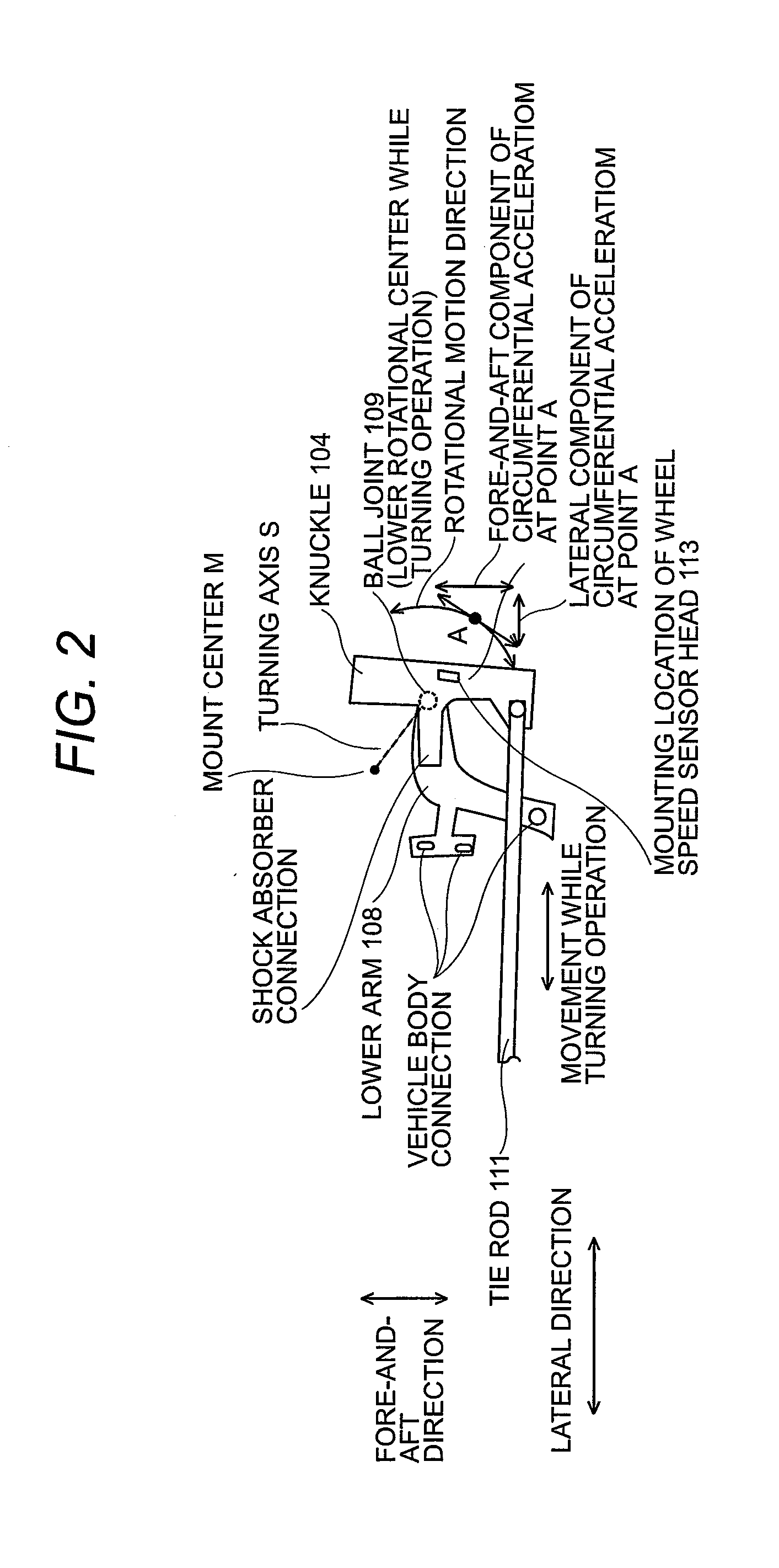
A motion control sensor system and motion control system for a moving unit have a physical quantity sensor in an unsprung mass of the moving unit so that physical quantities in the unsprung mass can be detected, bypassing the spring. An acceleration sensor for detecting acceleration exerted on the unsprung mass of the moving unit is placed so that its detection axis crosses the operation axis of the moving unit, so acceleration due to angular acceleration around the operation axis is not detected. Accordingly, the motion control sensor system and motion control system are suitable for running stability control during cornering of the moving unit.

Description

[0001]The present application is based on Japanese Patent Application No. 2008-232272 filed Sep. 10, 2008, the entire contents of which are incorporated herein by reference.TECHNICAL FIELD [0002]The present invention relates to a motion control sensor system, for a moving unit, that is suitable for running stability control during cornering of the moving unit, and also relates to a motion control system.BACKGROUND ART[0003]Systems have been developed, which control braking, driving, and maneuvering of the vehicles according to results of vehicle motion measurement, in order to improve braking and driving performance of vehicles and to increase their maneuvering stability[0004]Anti-lock braking systems and traction control systems are widely used, which use wheel speed sensors for detecting the rotational speeds of the wheels of a vehicle to suppress the wheels from locking or slipping.[0005]FIGS. 13 and 14 show conventional motion control systems on which wheel speed sensors are mou...

Claims


Application Information

Patent Timeline
IPC IPC(8): B60G17/0165B60R16/02B60T8/171B62D6/00G01P15/00
CPCB60G3/06B60G15/07B60G2200/142B60G2204/112B60G2204/113B60G2204/115B60T2260/06B60G2400/0523B60G2400/1042B60G2400/208B60G2401/902B60T8/171B60G2204/202
Inventor YAMAMOTO, SATOSHI
Owner HITACHI CABLE
Learn More