Sense amplifier circuit and semiconductor memory device
a technology of amplifier circuit and memory device, which is applied in the direction of digital storage, static storage, instruments, etc., can solve the problems of reduced voltage difference at the sense node ns in reading out high and low level data from memory cell mc, and inability to obtain sufficient operating margin. , to achieve the effect of improving the operating margin of sense amplifier circuit, improving the reliability of the operation, and excellent operating margin
- Summary
- Abstract
- Description
- Claims
- Application Information
AI Technical Summary
Benefits of technology
Problems solved by technology
Method used
Image
Examples
first embodiment
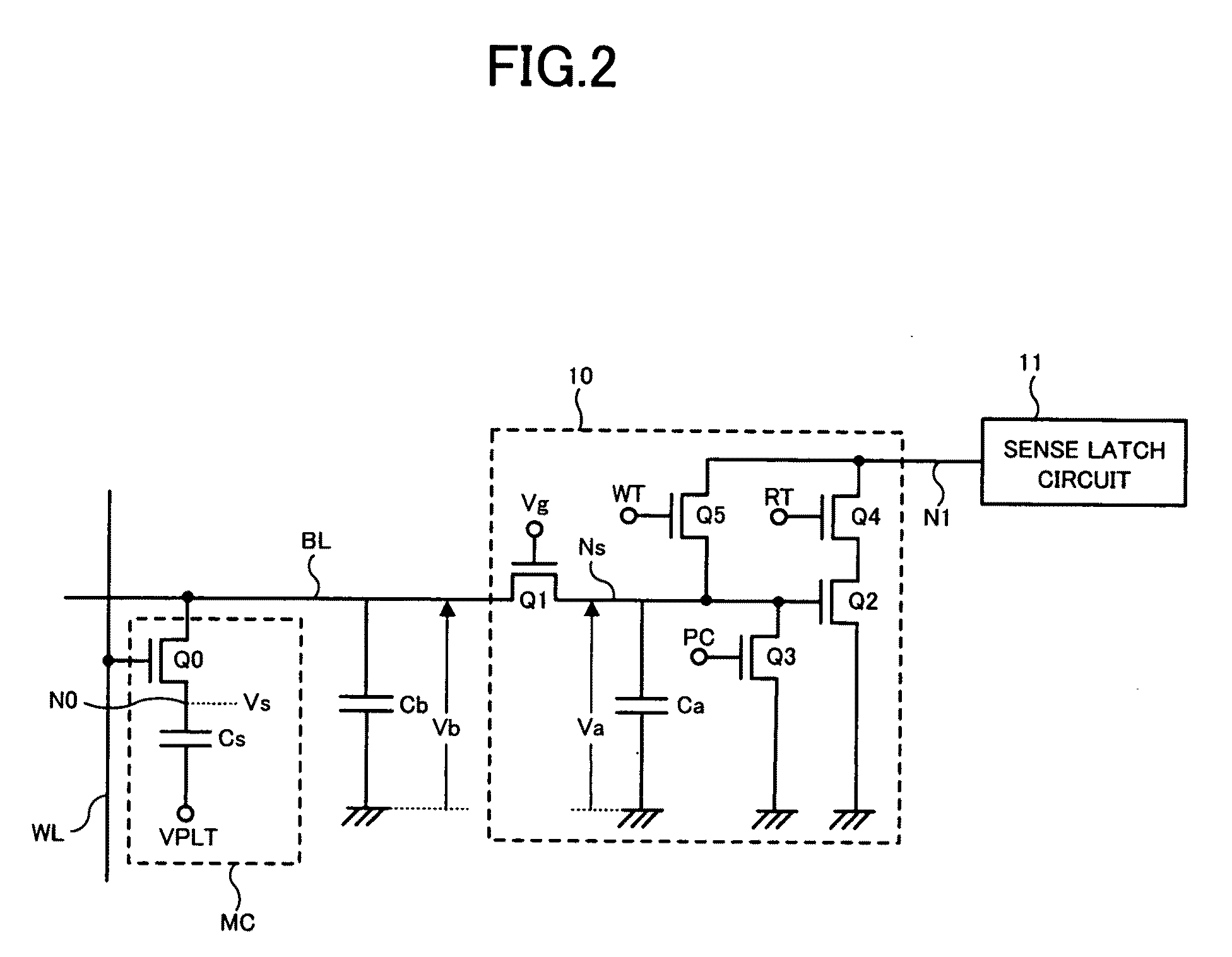
[0050]A first embodiment of the invention will be described below. A feature of the first embodiment is that a single-ended sense amplifier circuit controlled in the charge transfer mode and the charge distributing mode is employed. FIG. 2 shows a configuration example of a sensing part in a DRAM of the first embodiment, in which a memory cell MC, a preamplifier 10 (the first sense amplifier of the invention) functioning as the above basic operation of the sense amplifier circuit, and a sense latch circuit 11 (the second sense amplifier of the invention) located subsequent to the preamplifier 10 are shown.
[0051]The memory cell MC is a 1T1C type DRAM memory cell composed of an N-type MOS selection transistor Q0, and a capacitor Cs storing information as electric charge. The selection transistor Q0 has a source connected to the bit line BL and a gate connected to the word line WL. The capacitor Cs is connected between the drain of the selection transistor Q0 and a cell plate voltage V...
second embodiment
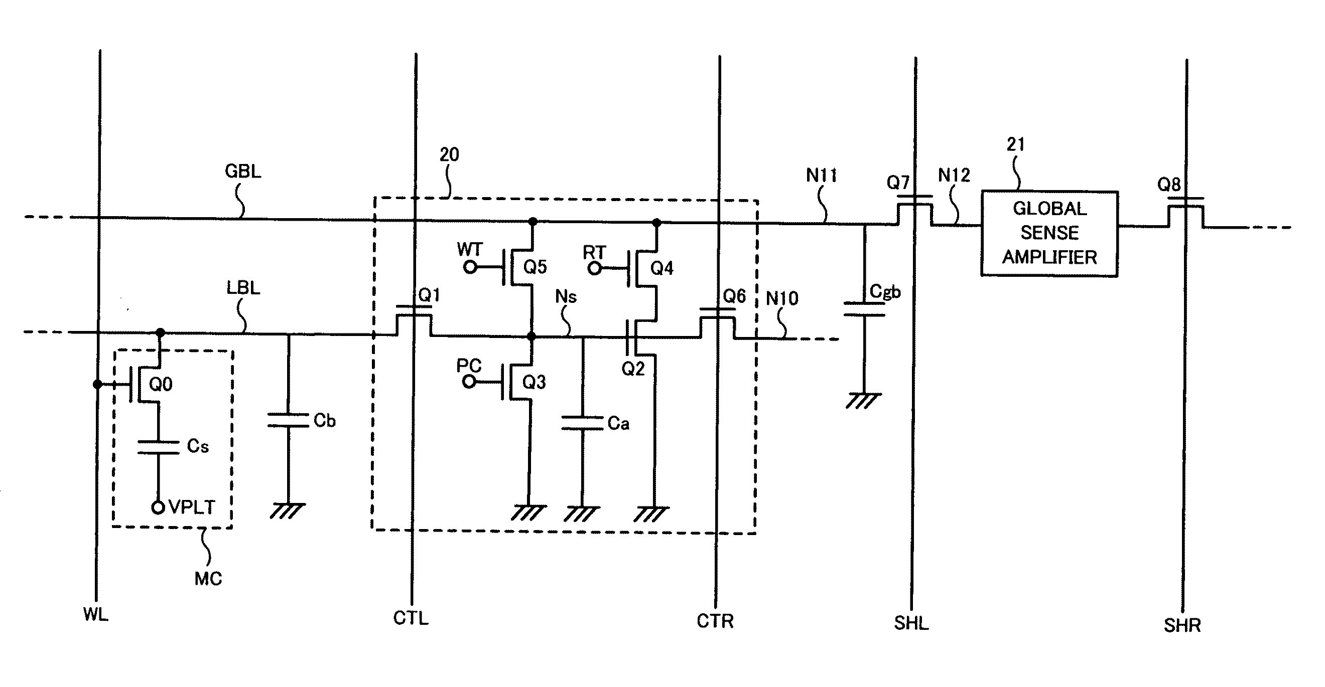
[0065]Next, a second embodiment of the invention will be described. In the second embodiment, a hierarchical memory cell array is formed, and a charge transfer / distributing type single-ended sense amplifier is applied to a DRAM having hierarchical bit lines and hierarchical sense amplifier circuits. FIG. 7 shows a configuration example of a sensing part in the DRAM of the second embodiment, in which a memory cell MC, a local bit line LBL and a global bit line GBL which serve as the hierarchical bit lines, and a local sense amplifier 20 and a global sense amplifier 21 which serve as the hierarchical sense amplifier circuits are respectively shown. The local bit line LBL connected to the memory cell MC is selectively connected the global bit line GBL via the local sense amplifier 20, and data thereof is transmitted to the corresponding global sense amplifier 21. Although FIG. 7 shows only part of the configuration, the second embodiment employs the configuration in which each local se...
third embodiment
[0087]Next, a third embodiment of the invention will be described. In a DRAM of the third embodiment, hierarchical bit lines and sense amplifier circuits are configured in the same manner as the second embodiment, part of which differs from the second embodiment. Although the circuit configuration in FIG. 7 of the second embodiment is almost common to the third embodiment, a configuration of certain power source circuits is modified. That is, a compensated voltage generating circuit which compensates fluctuation of the threshold voltage Vt1 of the MOS transistor Q1 and a compensated voltage generating circuit which compensates fluctuation of the threshold voltage Vt2 of the MOS transistor Q2 are employed. Specific configurations thereof will be described below.
[0088]FIG. 15 shows an example of a circuit configuration of the global sense amplifier 21 of the third embodiment. The basic circuit configuration in FIG. 15 is almost common to FIG. 8 of the second embodiment, in which howev...
PUM
 Abstract
Description
Claims
Application Information
 - R&D
- Intellectual Property
- Life Sciences
- Materials
- Tech Scout
- Unparalleled Data Quality
- Higher Quality Content
- 60% Fewer Hallucinations
Browse by: Latest US Patents, China's latest patents, Technical Efficacy Thesaurus, Application Domain, Technology Topic, Popular Technical Reports.
© 2025 PatSnap. All rights reserved.Legal|Privacy policy|Modern Slavery Act Transparency Statement|Sitemap|About US| Contact US: help@patsnap.com


