Radiation-proof resin composition and radiation-proof cable

Active Publication Date: 2010-03-04
HITACHI METALS LTD
View PDF1 Cites 11 Cited by
  • Summary
  • Abstract
  • Description
  • Claims
  • Application Information

AI Technical Summary

Benefits of technology

[0011]Accordingly, it is an object of the present invention to provide a radiation-proof resin composition that can be used as BWR and PWR sheath materials, is excellent in flame retardancy, heat resistance, radiation resistance and water-resistant property and can pass the test of the reversed sequential method, as well as a radiation-proof cable.
[0028]A radiation-proof resin composition in one embodiment of the invention is composed such that a carbon black and a baked clay with a predetermined grain size are added at a predetermined rate to a halogen-based polymer. Therefore, even when an ionic component is caused by radiation application and thermal deterioration, the baked clay can efficiently capture the ionic component and the carbon black can suppress the radiation-proof resin composition from being swollen due to water penetration into the radiation-proof resin composition.

Problems solved by technology

Electric wires and cables used in nuclear power stations, such as boiling water reactors (BWRs), or pressurized water reactors (PWRs), are exposed to heat and radiations during normal running of each nuclear reactor operated in specified running conditions, and also in the event of loss-of-coolant accidents, fires etc.
Here, when a polymer compound material containing a halogen such as chlorine is exposed to heat and radiations, the halogen is likely to desorb from the material.
Also, because as an evaluation method for cable covering materials, it is difficult to simultaneously apply heat and radiations to the cable covering materials because of requiring a special apparatus, the evaluation method uses sequential ageing (irradiation after thermal ageing).
The flame-retardant composition as disclosed in JP-A-S62-161850 is not intended for use in which radiation resistance is required, and it therefore cannot be used directly as a BWR sheath material or a PWR sheath material.

Method used


Image

  • Radiation-proof resin composition and radiation-proof cable
  • Radiation-proof resin composition and radiation-proof cable
  • Radiation-proof resin composition and radiation-proof cable

Examples


first embodiment

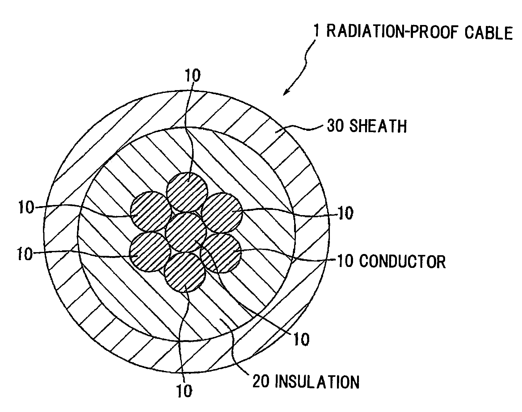
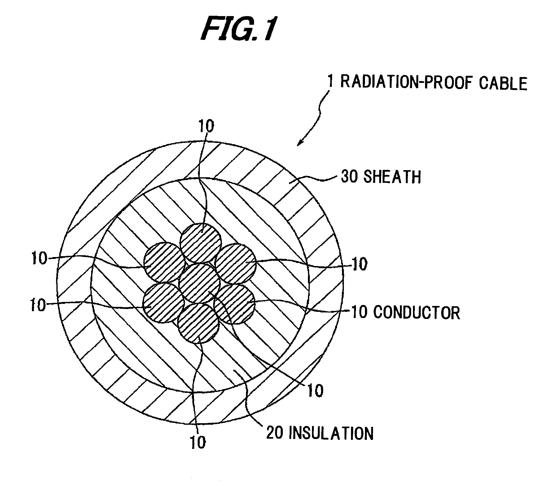
[0034]FIG. 1 is a cross sectional view showing a radiation-proof cable using a radiation-proof resin composition in a preferred first embodiment according to the invention

[0035]A radiation-proof resin composition in the first embodiment of the invention comprises a halogen-based polymer as a polymer containing chlorine, a radiation resistance providing agent for providing the halogen-based polymer with radiation resistance, an amorphous inorganic material for capturing an ionic component occurred in the halogen-based polymer by irradiation of radiations, and a reinforcing material having an insulation property, reinforcing the mechanical strength of the halogen-based polymer, and added to the halogen-based polymer not more than the additive amount of the amorphous inorganic material. The radiation-proof resin composition of the first embodiment may be formed by further adding a specified combination preparation.

[0036]A radiation-proof cable 1 of the embodiment comprises plural condu...

second embodiment

[0091]FIG. 2 is a schematic cross-sectional view showing a radiation-proof cable in the second embodiment according to the invention.

[0092]The radiation-proof cable la of the second embodiment is different from the radiation-proof cable 1 of the first embodiment in that the plural conductors 10 are each covered with an insulation 20, an intervening filler 40 is formed thereon, and a tape 50 is wound on the intervening filler 40, and the other components thereof are the same as those of the radiation-proof cable 1. The detailed explanation except about the difference will be omitted below.

[0093]The radiation-proof cable la comprises a three-wire core with plural conductors 10 (e.g., three conductors) with the insulation 20 formed on the periphery thereof, the intervening filler 40 formed on the three-wire core, the tape 50 as a press-holding tape wound on the periphery of the intervening filler 40, and a sheath 30 covering the tape 50. In the second embodiment, the sheath 30 is forme...

third embodiment

[0094]FIG. 3 is a schematic cross-sectional view showing a radiation-proof cable in the third embodiment according to the invention.

[0095]The radiation-proof cable 1b of the third embodiment is different from the radiation-proof cable 1a of the second embodiment in that it comprises a twisted pair wire 60 in which a conductor 10 covered with an insulation 20 is twisted, and the other components thereof are the same as those of the radiation-proof cable 1. The detailed explanation except about the difference will be omitted below.

[0096]The radiation-proof cable 1b comprises a first wire core and a second wire core with plural conductors 10 (e.g., two conductors) with the insulation 20 formed on the periphery thereof, twisted pair wires 60 with the first and second wire cores twisted, a shield layer 70 formed of a metal material and covering the twisted pair wires 60, and a sheath 30 covering the shield layer 70. In the third embodiment, the sheath 30 is formed of the radiation-proof ...


PUM

PropertyMeasurementUnit
Fractionaaaaaaaaaa
Fractionaaaaaaaaaa
Percent by massaaaaaaaaaa

Abstract

A radiation-proof resin composition includes a polymer containing chlorine, a radiation resistance providing agent for providing the polymer with a radiation resistance, an amorphous inorganic material for capturing an ionic component generated in the polymer by radiation application, and a reinforcing material for reinforcing a mechanical strength of the polymer. An amount of the reinforcing material is not more than that of the amorphous inorganic material.

Description

[0001]The present application is based on Japanese patent application No.2008-219723 filed Aug. 28, 2008, the entire contents of which are incorporated herein by reference.BACKGROUND OF THE INVENTION[0002]1. Field of the Invention[0003]The present invention relates to a radiation-proof resin composition and a radiation-proof cable. In particular, it relates to a radiation-proof resin composition and a radiation-proof cable, which are excellent in water-resistant property.[0004]2. Description of the Related Art[0005]Electric wires and cables used in nuclear power stations, such as boiling water reactors (BWRs), or pressurized water reactors (PWRs), are exposed to heat and radiations during normal running of each nuclear reactor operated in specified running conditions, and also in the event of loss-of-coolant accidents, fires etc. Accordingly, in case of these accidents, electric wires and cables used in the nuclear power stations are required to have high flame retardancy and radiat...

Claims


Application Information

Patent Timeline
IPC IPC(8): H01B3/30C08K3/34C08L41/00C08L27/04
CPCC08K3/34C08K5/0008H01B3/448C08L2201/02H01B3/441C08L23/16
Inventor SORIMACHI, MASAMINAKAMURA, YOSHIAKIKIMURA, HITOSHIMATSUYAMA, SHIGEKI
Owner HITACHI METALS LTD
Why Eureka
Try Eureka