Heat exchanger and its manufacturing method
a heat exchanger and manufacturing method technology, applied in the field of heat exchangers, can solve the problems of increasing the cost of heat exchangers, and achieve the effects of improving the reliability of heat exchangers, providing inexpensively, and being easy to manufactur
- Summary
- Abstract
- Description
- Claims
- Application Information
AI Technical Summary
Benefits of technology
Problems solved by technology
Method used
Image
Examples
first exemplary embodiment
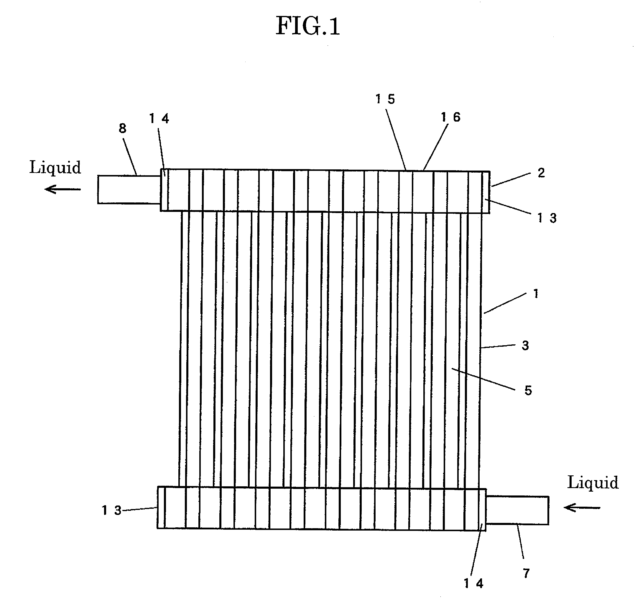
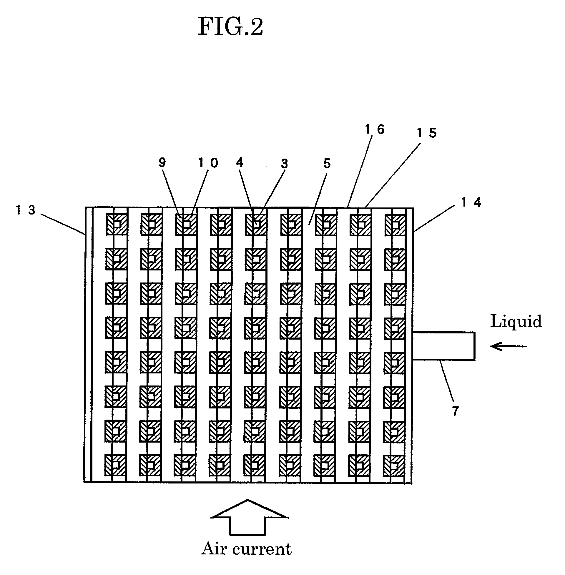
[0103]FIG. 1 is a front view of a heat exchanger in accordance with exemplary embodiment 1 of the present invention. FIG. 2 is a sectional view of a heat exchanging section in the direction orthogonal to the tube axis in the heat exchanger. FIG. 3 is a sectional view of the heat exchanging section in the tube axis direction in the heat exchanger.
[0104]In FIG. 1 through FIG. 3, the heat exchanger has heat exchanging section 1, and header sections 2 disposed at opposite ends of heat exchanging section 1. Heat exchanging section 1 has tubes 3 arranged in a grid shape, tube internal flow channels 4, and tube external flow channels 5. Header sections 2 include branch flow channels 6, inflow tube 7, and outflow tube 8. Tube internal flow channels 4 are connected to branch flow channels 6. Each tube 3 has a substantially square cross section, and has band-like long plate 9 and long plate 10 having U-shaped cross section. Each branch flow channel 6 is formed by continuously interconnecting ...
second exemplary embodiment
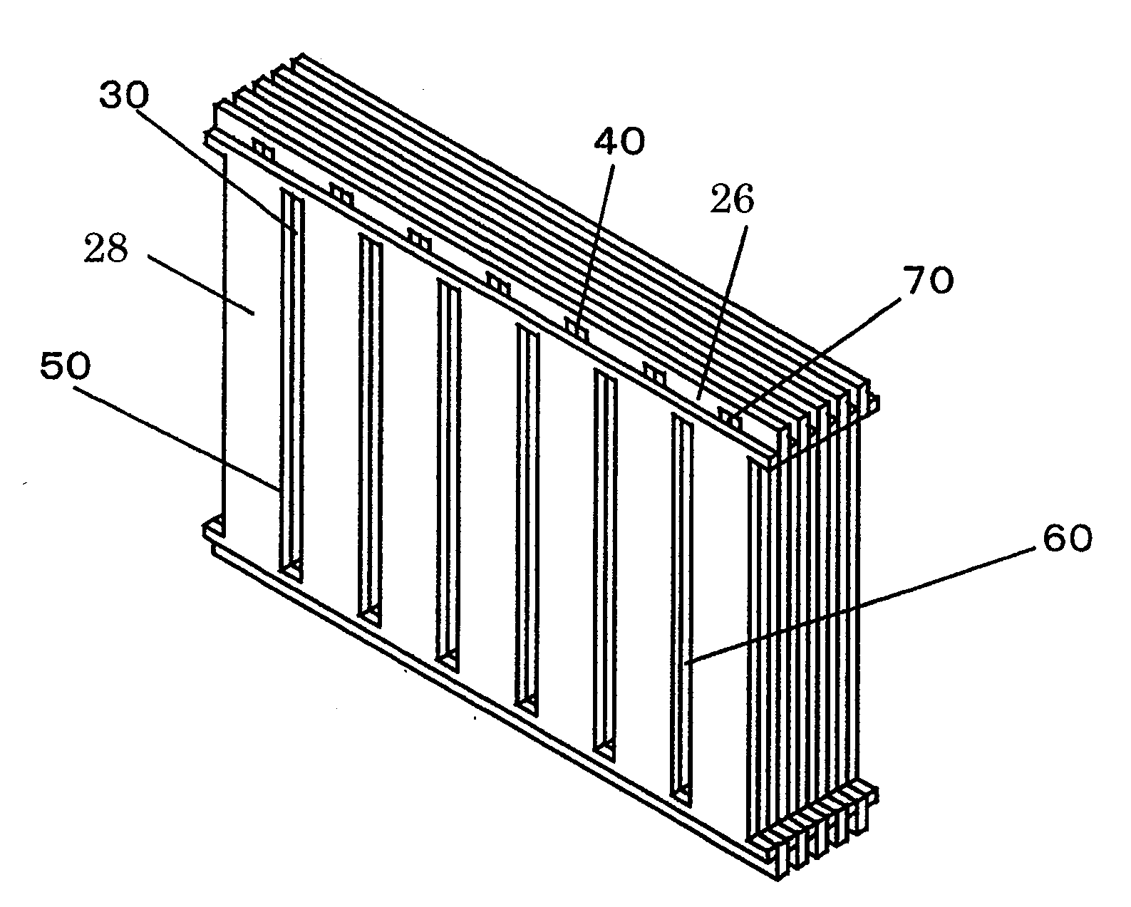
[0118]FIG. 11 is a perspective view of a heat exchanging section in accordance with exemplary embodiment 2 of the present invention.
[0119]FIG. 12 is a front view of a first substrate in accordance with exemplary embodiment 2. FIG. 13 is a front view of a second substrate in accordance with exemplary embodiment 2. The heat exchanging section is formed by alternately stacking first substrates 26 and second substrates 28. A plurality of first slits 30 and a plurality of second slits 40 are alternately arranged substantially in parallel on each first substrate 26. Third slits 50 having the same shape as that of first slits 30 are disposed on each second substrate 28 at the same positions as the projection positions of first slits 30.
[0120]First slits 30 and third slits 50 overlap each other on the projection plane and communicate with each other, thereby forming tube external flow channels 60. The longitudinal size of third slits 50 disposed on second substrate 28 is shorter than that o...
third exemplary embodiment
[0132]FIG. 19 is a perspective view of a heat exchanging section in accordance with exemplary embodiment 3 of the present invention. The heat exchanging section is formed by stacking first substrates 126 and second substrates 128 so that first substrates 126 are sandwiched between second substrates 128. First slits 130 and third slits 150 form tube external flow channels 160 similarly to embodiment 2. Second slits 140 and second substrates 128 form tube internal flow channels 170. Three first substrates 126 are stacked between second substrates 128 on the inflow side of the external fluid, two first substrates 126 are stacked between them in the intermediate part, and one first substrate 126 is disposed between them on the outflow side thereof. Thus, tube internal flow channels 170 are enlarged in the substrate stacking direction on the inflow side of the external fluid.
[0133]Three rows of first substrates 126 are disposed in the flow direction of the external fluid in embodiment 3;...
PUM
 Abstract
Description
Claims
Application Information
 - R&D
- Intellectual Property
- Life Sciences
- Materials
- Tech Scout
- Unparalleled Data Quality
- Higher Quality Content
- 60% Fewer Hallucinations
Browse by: Latest US Patents, China's latest patents, Technical Efficacy Thesaurus, Application Domain, Technology Topic, Popular Technical Reports.
© 2025 PatSnap. All rights reserved.Legal|Privacy policy|Modern Slavery Act Transparency Statement|Sitemap|About US| Contact US: help@patsnap.com


