
Permanent magnet and method of manufacturing same

a permanent magnet and magnet technology, applied in the field of permanent magnets, can solve the problems of remarkable deterioration in the magnetic properties, inability to improve the magnetic properties, and the magnetic properties are demagnetized, and achieve the effects of high productivity, high magnetic properties, and efficient diffusion

Active Publication Date: 2010-03-04
ULVAC INC
View PDF5 Cites 7 Cited by
  • Summary
  • Abstract
  • Description
  • Claims
  • Application Information

AI Technical Summary

Benefits of technology

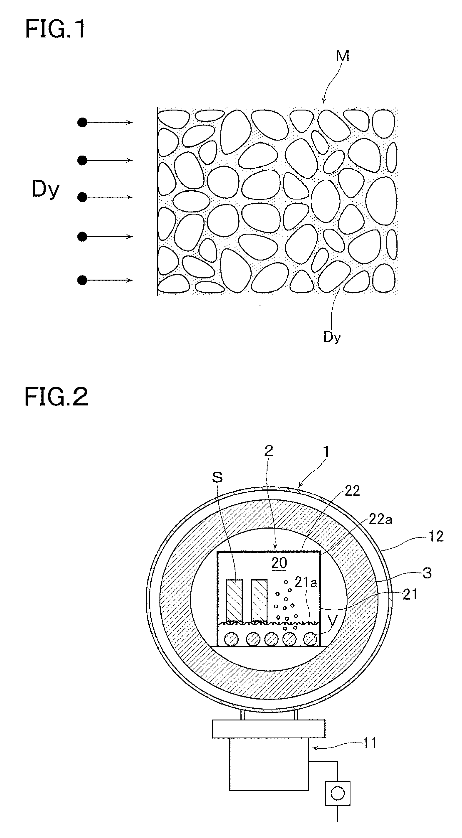
[0026]As described hereinabove, the method of manufacturing a permanent magnet according to this invention has the effects in: that Dy and / or Tb adhered to the surface of the sintered magnet containing therein a lubricant can be efficiently diffused into the grain boundary phase; and that a permanent magnet having a high productivity and high magnetic properties can be manufactured. Further, the permanent magnet according to this invention has an effect in that it has high magnetic properties and has a particularly high coercive force.

Problems solved by technology

On the other hand, since the Curie temperature of the above-described sintered magnet is as low as about 300° C., there is a problem in that the Nd—Fe—B sintered magnet sometimes rises in temperature beyond a predetermined temperature depending on the circumstances of service of the product to be employed and therefore that it will be demagnetized by heat when heated beyond the predetermined temperature.
There is then another problem in that this fabrication gives rise to defects (cracks and the like) and strains to the grains of the sintered magnet, resulting in a remarkable deterioration in the magnetic properties.
At the time of compression molding by a pair of punches, due to friction among the alloy raw meal powder that is filled into the cavity and due to friction between the alloy raw meal powder and the wall surfaces of the die that is set in position in the punch, a high orientation cannot be obtained, resulting in a problem in that the magnetic properties cannot be improved.

Method used


Image

  • Permanent magnet and method of manufacturing same
  • Permanent magnet and method of manufacturing same
  • Permanent magnet and method of manufacturing same

Examples


example 1

[0060]As a Nd—Fe—B based sintered magnet, there was used one whose composition was 20Nd-5Pr-2Dy-1B-1Co-0.2Al-0.05Cu-0.1Nb-0.1Mo-bal.Fe and was fabricated into a rectangular parallelepiped of 5×40×40 mm. In this case, Fe, Nd, Pr, Dy, B, Co, Al, Cu, Nb and Mo were formulated in the above-described composition ratio to manufacture an alloy of 30 mm by a known centrifugal casting method. The alloy was once roughly ground in a known hydrogen grinding step and was subsequently finely ground by a jet mill fine grinding step, thereby obtaining an alloy raw meal powder.

[0061]Subsequently, this alloy raw meal powder was agitated by adding, in a mixing ratio of 0.05 wt %, a mixture of lubricant of a fatty acid based compound and a fatty acid metal salt lubricant; was filled into a cavity of a known a uniaxial pressurizing type of compression molding machine; and was formed into a predetermined shape in a magnetic field (forming step). The molded body thus obtained was disposed in a known sinte...


PUM

PropertyMeasurementUnit
Grain sizeaaaaaaaaaa
Lengthaaaaaaaaaa
Temperatureaaaaaaaaaa

Abstract

There is provided a method of manufacturing a permanent magnet in which Dy and / or Tb adhered to the surface of a sintered magnet containing a lubricant can be efficiently diffused and in which the permanent magnet having high magnetic properties can be manufactured at good productivity. The permanent magnet is manufactured by executing a first step of adhering at least one of Dy and Tb to at least a part of a surface of a sintered magnet made by sintering iron-boron-rare earth based alloy raw meal powder containing a lubricant; and a second step of heat-treating the sintered magnet at a predetermined temperature to thereby disperse at least one of Dy and Tb adhered to the surface of the sintered magnet into grain boundary phase of the sintered magnet. At this time, as the sintered magnet, there is used one manufactured in an average grain size within a range of 4 μm˜8 μm.

Description

[0001]This application is a national phase entry under 35 U.S.C. §371 of PCT Patent Application No. PCT / JP2007 / 74407, filed on Dec. 19, 2007, which claims priority under 35 U.S.C. §119 to Japanese Patent Application No. 2006-344782, filed Dec. 21, 2006, both of which are incorporated by reference.TECHNICAL FIELD[0002]The present invention relates to a permanent magnet and a method of manufacturing the permanent magnet, and more particularly relates to a permanent magnet having high magnetic properties in which Dy and / or Tb is diffused into grain boundary phase of a Nd—Fe—B based sintered magnet, and to a method of manufacturing the permanent magnet.BACKGROUND ART[0003]A Nd—Fe—B based sintered magnet (so-called neodymium magnet) is made of a combination of iron and elements of Nd and B that are inexpensive, abundant, and stably obtainable natural resources and can thus be manufactured at a low cost and additionally has high magnetic properties (its maximum energy product is about 10 ...

Claims


Application Information

Patent Timeline
IPC IPC(8): H01F41/02H01F1/053H01F1/08
CPCC22C38/005C22C38/06C22C38/10H01F41/0293C22C38/16H01F1/0577C22C38/12H01F1/08H01F41/02
Inventor NAGATA, HIROSHISHINGAKI, YOSHINORI
Owner ULVAC INC
Learn More