
Control apparatus and control method for hybrid vehicle

a control apparatus and hybrid technology, applied in the direction of motor/generator/converter stopper, multiple dynamo-motor starters, electric devices, etc., can solve the problems of excessive processing load, control configuration, and loss of synchronization between a plurality of electric motors in terms,

Active Publication Date: 2010-02-25
TOYOTA JIDOSHA KK +1
View PDF4 Cites 30 Cited by
  • Summary
  • Abstract
  • Description
  • Claims
  • Application Information

AI Technical Summary

Benefits of technology

[0023]As seen from above, a chief advantage of the present invention is that the control apparatus for a hybrid vehicle configured to include control units (ECU) provided separately for respective electric motors can appropriately perform the electric power balance control for restricting the total electric power of the electric motors within a predetermined range while eliminating the influence of the communication time delay between the control units.
is that the control apparatus for a hybrid vehicle configured to include control units (ECU) provided separately for respective electric motors can appropriately perform the electric power balance control for restricting the total electric power of the electric motors within a predetermined range while eliminating the influence of the communication time delay between the control units.

Problems solved by technology

As for the actual motor drive control apparatus, however, if a single control apparatus (electronic control unit: ECU for example) is used to perform control operation for both of motors M1 and M2, an excessively heavy processing load is placed on the ECU, and accordingly a high-performance ECU may be required.
In the case, however, where control apparatuses (ECU) are provided separately and independently for respective electric motors, a problem arises when motor M1 and motor M2 are cooperatively controlled.
The control configuration, however, could lose synchronization between a plurality of electric motors in terms of the data and information used for the electric power balance control, due to an influence of the time for communication between the control apparatus performing the electric power balance control and other control apparatuses.
In other words, recognition of data and information is delayed by the time consumed for communication.
As a result, particularly in a period in which the electric motor output (rotational speed, torque) varies, the possibility that appropriate electric power balance control is impossible cannot be denied.

Method used


Image

  • Control apparatus and control method for hybrid vehicle
  • Control apparatus and control method for hybrid vehicle
  • Control apparatus and control method for hybrid vehicle

Examples


Embodiment Construction

[0037]Embodiments of the present invention will be hereinafter described in detail with reference to the drawings. In the drawings, like or corresponding components are denoted by like reference characters, and a detailed description thereof will not be repeated in principle.

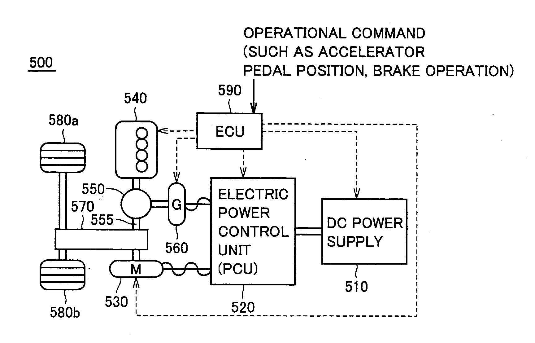
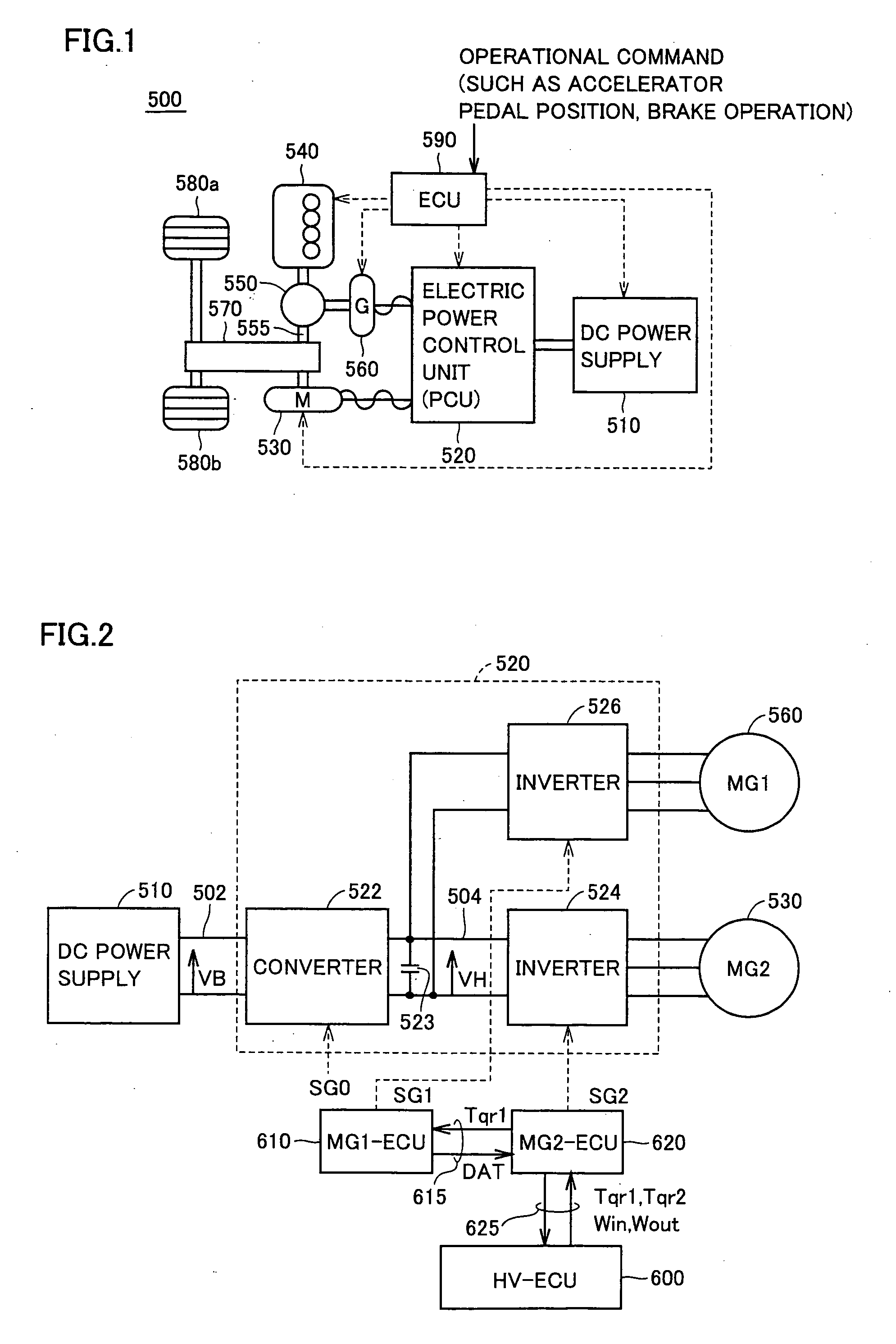
[0038]FIG. 1 is a schematic block diagram showing the entire configuration of a hybrid vehicle controlled by a control apparatus for a hybrid vehicle according to an embodiment of the present invention.

[0039]Referring to FIG. 1, hybrid vehicle 500 includes a DC (direct current) power supply 510, an electric power control unit (PCU) 520 performing electric power conversion for driving a motor, a motor generator 530 mainly operating as an electric motor, an engine 540, a power split device 550, a motor generator 560 mainly operating as an electric generator, a reduction gear unit 570, drive wheels 580a, 580b, and an ECU 590 controlling the whole operation of hybrid vehicle 500.

[0040]Motor generators 530, 560 corre...


PUM


Abstract

A first motor generator-control unit (MG1-ECU) and a second motor generator-control unit (MG2-ECU) are provided independently for respective motor generators. The MG2-ECU performs electric power balance control by correcting an MG2 torque command value as required, so that the sum of the MG1 electric power and the MG2 electric power is within a range of allowable input / output electric power of a DC power supply. The electric power balance control is performed using an estimate of the MG1 electric power based on data obtained by the MG1-ECU. The estimate is determined so that a communication delay time between the MG1-ECU and the MG2-ECU is corrected. In this way, the electric power balance control can be performed appropriately for restricting, within a predetermined range, the total input / output electric power of the electric motors as a whole of a hybrid vehicle mounted with a plurality of motor generators (electric motors).

Description

TECHNICAL FIELD[0001]The present invention relates to a control apparatus for a hybrid vehicle, and more particularly to a control apparatus for a hybrid vehicle configured to include a control unit (ECU) provided independently for each electric motor.BACKGROUND ART[0002]A motor drive control apparatus driving and controlling a plurality of electric motors has been used as one type of the motor drive control apparatus applied to a hybrid vehicle. International Publication No. WO2003 / 015254 for example discloses in FIG. 9 a configuration of a motor drive control apparatus used for a hybrid vehicle of a two-motor system including electric motors M1 and M2.[0003]FIG. 9 of International Publication No. WO2003 / 015254 conceptually shows a common control apparatus as the control apparatus for driving and controlling electric motors M1 and M2. As for the actual motor drive control apparatus, however, if a single control apparatus (electronic control unit: ECU for example) is used to perform...

Claims


Application Information

Patent Timeline
Patent Type & Authority Applications(United States)
IPC IPC(8): H02P6/04B60L50/16
CPCB60K6/445B60L15/20B60W10/06B60W10/08B60W20/00Y02T10/7275Y02T10/6239Y02T10/6286Y02T10/646Y02T90/16Y02T10/648B60W30/184B60L1/00B60L2220/42B60L2240/421B60L2240/423B60L2240/80B60L2260/28B60L2260/44Y02T10/72B60L50/61B60L50/16Y02T10/62Y02T10/64Y02T10/7072Y02T10/70B60W30/18127B60W20/13
Inventor YAMADA, KENJIITOH, TAKESHI
Owner TOYOTA JIDOSHA KK
Learn More