Power source device and magnetic resonance imaging apparatus using the same

a technology of magnetic resonance imaging and power source device, which is applied in the direction of power conversion systems, instruments, magnetic measurements, etc., can solve the problems of enlarged circuit scale, achieve high accuracy, short rise and fall time, and accelerate image taking speed of mri apparatus

Inactive Publication Date: 2010-02-25
HITACHI LTD
View PDF0 Cites 27 Cited by
  • Summary
  • Abstract
  • Description
  • Claims
  • Application Information

AI Technical Summary

Benefits of technology

[0015]In the power source device constituted in the above manner, with the AC-DC converting and voltage stepping up means, the voltage obtained through full wave rectification of the commercial AC power source voltage is stepped up to a higher voltage, the stepped up DC voltage is converted to AC voltages by the DC-AC converting means, these AC voltages are stepped up by the transformers while insulating each other and after smoothing the same and connecting the DC voltages in series, the DC voltage power source is obtained and constituted, thus, if an operating frequency of the AC-DC converting and voltage stepping up means and the DC-AC converting means, which use semiconductor switches is shifted to a high frequency side to about 20 kHz, the sizes of the insulating transformers and smoothing means are reduced extremely, thereby, the size and cost of the DC voltage power source means, which is insulated from the commercial AC power source can be reduced.
[0017]In the DC-AC converting means (which corresponds to a phase shift inverter circuit 7, 60 and 70 in embodiments), since the not less than two sets of full bridge inverter circuits are constituted by the plural arms and the conduction phase of the semiconductor switches in the remaining arms is controlled in a delayed phase and / or in an advanced phase with respect to the conduction phase of the semiconductor switches in the common arm, the number of the semiconductor switches is reduced and moreover, the loss in the semiconductor switches is reduced, thereby, a small sized DC-AC converting means can be constituted.
[0019]Thereby, the DC voltage of the DC power source means shows a stable power source voltage without variation and a stable current with a short rise time can be fed to a load by the multi level inverter using the DC power source.
[0023]Through controlling in this manner, a variation in the output voltage of the chopper circuit is prevented and the input DC power source voltage to the DC-AC converting means can be kept at a constant voltage which can otherwise vary due to such as a variation of the commercial AC power source voltage and others, thereby, the DC-AC converting means can be operated stably.
[0027]Through the use of such AC-DC converting and voltage stepping up means, the output voltage can be stepped up to a same voltage as of the AC-DC converting and voltage stepping up means as explained in (4) and further the number of the elements constituting the circuit is reduced. Further, the power factor is improved to lessen the apparent power and the amount of current flowing through the semiconductor switches is permitted to be small as well as the capacity of the commercial AC power source installation can be reduced.
[0029]With thus constituted power source device for the coils for generating the magnetic fields, a highly accurate high voltage and large current can be obtained while being insulated from the commercial AC power source, thereby, the intensity of the pulse like gradient magnetic fields can be increased and the magnetic fields having a short rise and fall time can be obtained, accordingly, the image taking speed by the MRI apparatus can be accelerated and the image taking time can be shortened.

Problems solved by technology

Further, in order to constitute the DC voltage power sources serially connected in multi stages, for example, when a full bridge inverter circuit as disclosed, for example, in JP-A-5-159893 is used, a problem arose that the circuit scale thereof enlarges because not less than eight sets of transistors and diodes are necessitated.

Method used


Image

  • Power source device and magnetic resonance imaging apparatus using the same
  • Power source device and magnetic resonance imaging apparatus using the same
  • Power source device and magnetic resonance imaging apparatus using the same

Examples


first embodiment

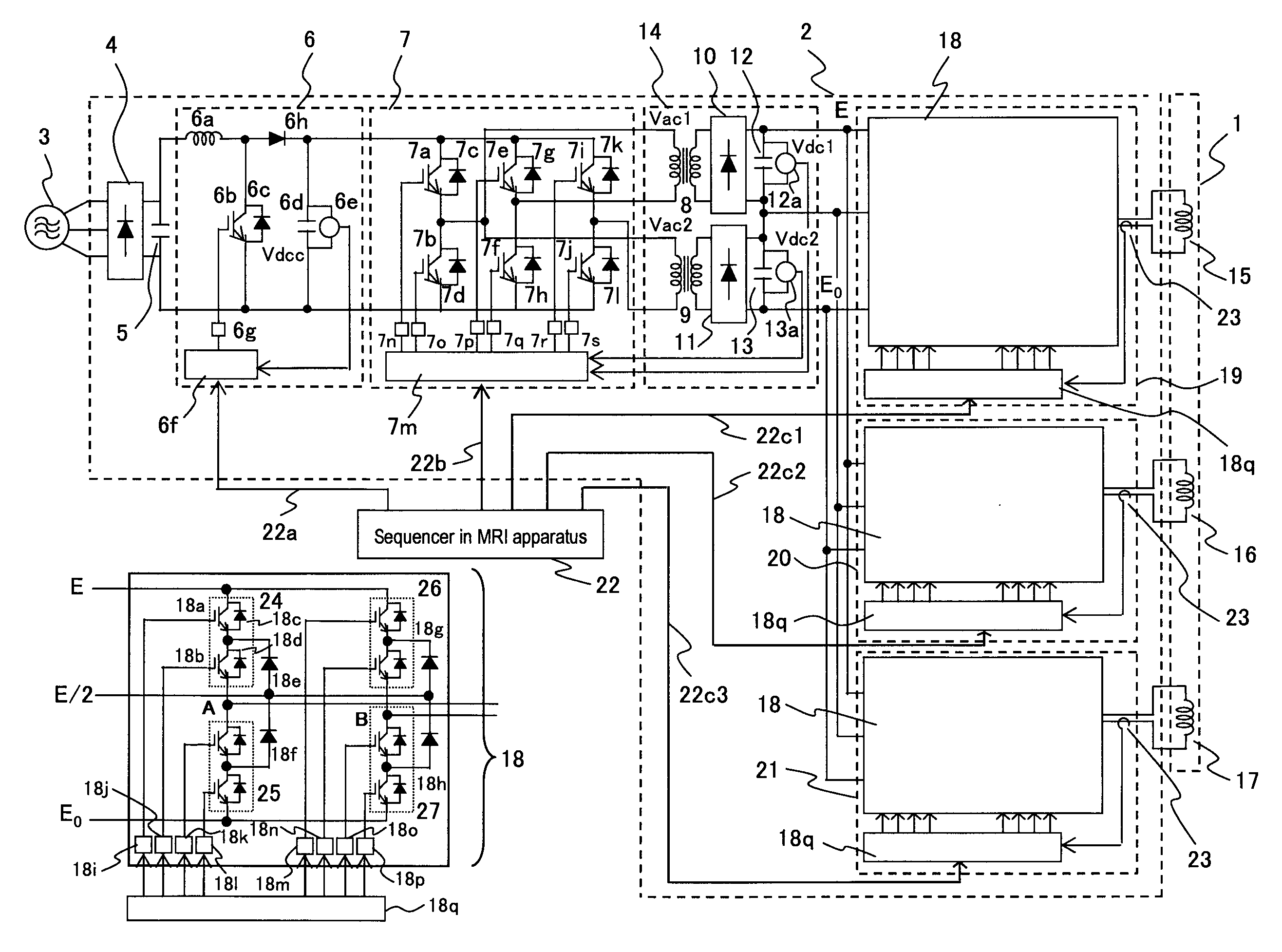
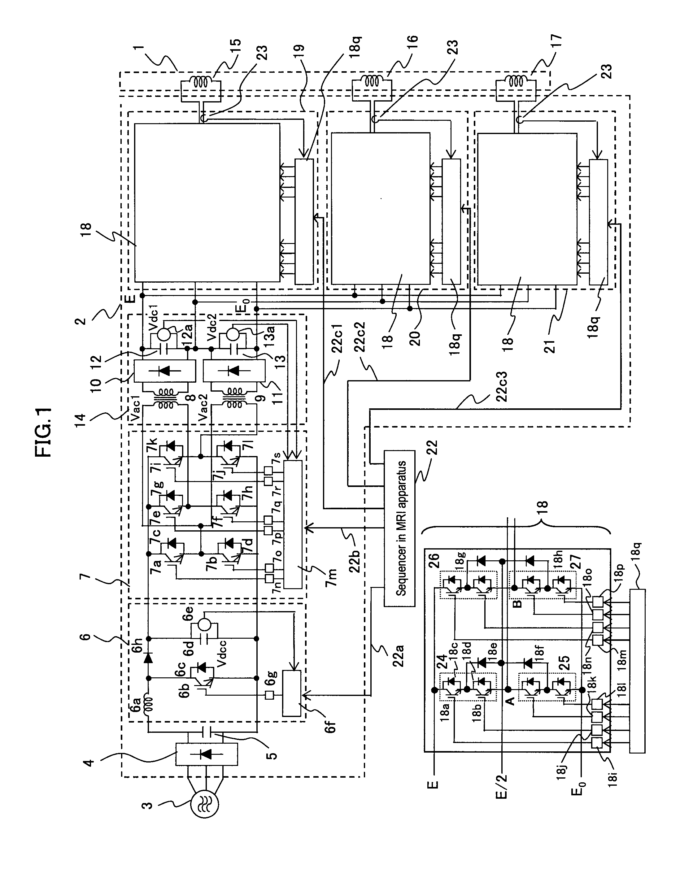
[0039]FIG. 1 is a circuit configuration diagram of a power source device for gradient magnetic fields in an MRI apparatus representing a first embodiment for a power source device according to the present invention.

[0040]A gradient magnetic field power source device 2 is constituted to receive an electric power supply from a three phase AC power source 3 and to feed an electric current to a gradient magnetic field coil 1 serving as a load, and is constituted by being provided with a first AC-DC converter 4 that is connected to the three phase AC power source 3 and converts a three phase AC voltage to a DC voltage, a first smoothing capacitor 5 that is connected to the output side of the AC-DC converter 4 and smoothes the DC voltage, a DC-DC converter (herein below will be called as a voltage step up type chopper circuit) 6 that is connected to the first smoothing capacitor 5 and steps up the smoothed DC voltage to a predetermined DC voltage, a DC-AC converter (herein below will be c...

second embodiment

[0116]FIG. 6 is a circuit constitution diagram of a gradient magnetic field power source device for an MRI apparatus representing a power source device according to the present invention.

[0117]Among the constitutional elements for generating a high DC voltage, since the constitution up to the step up chopper circuit 6 is the same as that in the first embodiment as shown in FIG. 1, in FIG. 6, only a phase shift inverter circuit 60 and an AC-DC step up and converting unit 50 are illustrated, and as the multi level PWM inverter circuit receiving the output of the AC-DC step up and converting unit 50, a multi level PWM inverter circuit 30 of 5 levels is used and to which output side the X axis coil 15 is connected as the load thereof. Further, the semiconductor switching control device for the circuit 30 and a circuit for driving the semiconductor switches in the multi level PWM inverter circuit 30 after amplifying the output signal from the device above are omitted.

[0118]Still further,...

third embodiment

[0136]FIG. 7 is a circuit constitution diagram of a gradient magnetic field power source device for an MRI apparatus representing a power source device according to the present invention.

[0137]In the third embodiment, since only a major portion of a phase shift inverter circuit 70 is different from that of the second embodiment as shown in FIG. 6 and the others thereof are the same as those in the second embodiment, herein, only the constitution of the phase shift inverter circuit 70 will be explained.

[0138]The phase shift inverter circuit 70 in FIG. 7 uses two sets of phase shift inverter circuits 7 in the first embodiment as shown in FIG. 1 and converts the output voltage Vdcc from the step up chopper circuit 6 into four voltages Vdc3, Vdc4, Vdc5 and Vdc6.

[0139]Namely, with the arm 1 formed by semiconductor switches 70a and 70b, the arm 2 formed by semiconductor switches 70c and 70d and the arm 3 formed by semiconductor switches 70e and 70f, two sets of full bridge inverter circui...


PUM


Abstract

A DC high voltage power source is constituted by an AC-DC converting means (4, 6) that converts a voltage of a commercial AC power source (3) to a DC voltage and steps up the converted DC voltage, a DC-AC converting means (7) that converts the DC voltage stepped up by the previous means to an AC voltage, two insulating transformer (8, 9) that steps up the AC voltage converted by the previous converting means while insulating each others and a series connection of DC voltages obtained after converting the output voltages from the transformers to DCs and smoothing the same. The DC voltage of the DC high voltage power source is used as the power source to current amplifiers (19, 20, 21) constituted by a multi level PWM inverter circuit (18) of 3 levels and the currents flowing through X axis, Y axis and Z axis gradient magnetic field coil (15, 16, 17) in an MRI apparatus connected to these current amplifiers as loads are controlled by a switching control device (18q) so as to meet with current command values (22c1, 22c2, 22c3) from a sequencer 22 in the MRI apparatus. As a result, plural DC high voltage power sources necessary for the multi level PWM inverter is constituted by a comparatively simple circuit, in addition, while suppressing loss in the power sources, a small sized and highly accurate high voltage and large current power source device and a magnetic resonance imaging apparatus using the same are provided.

Description

FIELD OF THE INVENTION[0001]The present invention relates to a power source device and in particular relates to a power source device that is suitable for varieties of power sources necessary for generating static magnetic fields, gradient magnetic fields and high frequency magnetic fields for a magnetic resonance imaging apparatus (herein below will be called as an MRI apparatus) requiring a high voltage and a large current, and an MRI apparatus using the same.CONVENTIONAL ART[0002]An MRI apparatus is one that which pulse like high frequency magnetic fields are applied to an inspection object which is placed in static magnetic fields, detects nuclear magnetic resonance signals generated from the inspection object and forms such as spectra and images based on the detected signals.[0003]The MRI apparatus is provided with, as its magnetic fields generating coils, super-conducting coils for generating static magnetic fields, gradient magnetic field coils for generating the gradient mag...

Claims


Application Information

Patent Timeline
IPC IPC(8): H02J3/00
CPCG01R33/3614H02M7/483G01R33/3852G01R33/383
Inventor HISHIKAWA, SHINGODOMOTO, TAKUYA
Owner HITACHI LTD
Why Eureka
Try Eureka