
Method for measuring tire, tire measuring device and tire building apparatus

a technology for measuring devices and tires, applied in the direction of instruments, other domestic objects, transportation and packaging, etc., can solve the problems of increasing the time required for the tire building process including the measurement time, the inability to obtain the intended profile, and the inability to build tires with a regular profile, so as to achieve the effect of preventing the occurrence of defective products and high accuracy

Inactive Publication Date: 2010-02-25
BRIDGESTONE CORP
View PDF7 Cites 15 Cited by
  • Summary
  • Abstract
  • Description
  • Claims
  • Application Information

AI Technical Summary

Benefits of technology

[0026]The measuring device of the present invention is mounted on the laminating apparatus capable of moving in a plane and rotating in the same plane (orientation change), i.e., triaxial movement. Thus, the entire surface of the tire including the side surfaces can be measured while the rubber strip is laminated, without requiring a special driving unit or an extra space for the measuring device. In addition, because the tire can be precisely measured with respect to the overall profile while being built, whether the data is good or bad can be determined with a higher accuracy. Thus, the occurrence of defective products can be more assuredly prevented.

Problems solved by technology

However, if the setting is inappropriate or if the tire building apparatus does not operate according to the setting, an intended profile cannot be obtained.
Thus, a tire having a regular profile may not be built.
However, these methods have a problem in that, because the profile is measured after the green tire is built, the time required for the tire building process including the measurement time increases.
There is also a problem in that, if the sensor is disposed as a device separate from the tire building apparatus, the space therefor is necessary.
Thus, not only that the measurement itself is time consuming, but also that, because the measurement is performed after building, whether or not the building is successful cannot be known during wrapping, and sometimes the tire is determined to be defective after the tire is built.
This results in a problem in that the material and processing time having been consumed are wasted.
However, in this measuring device, because the sensors are mounted on the traverse unit that reciprocates in the width direction of the tire building drum, the traveling direction of the sensors is limited to the traverse direction, i.e., the X-axis direction.
Therefore, this measuring device measures the tire to be formed only in the width direction, and cannot measure the side surfaces thereof.
That is, it is impossible for this measuring device to measure a portion at a certain distance from the laser displacement gauge being used, and, due to the principle of reflection of the laser displacement gauge, it is impossible to perform measurement unless the gradient of an end surface is ±45°.
Therefore, even if the measuring device is moved along the tire in the traverse direction, the side surfaces of the tire cannot be measured.

Method used


Image

  • Method for measuring tire, tire measuring device and tire building apparatus
  • Method for measuring tire, tire measuring device and tire building apparatus
  • Method for measuring tire, tire measuring device and tire building apparatus

Examples


Embodiment Construction

[0036]A measuring device according to an embodiment of the present invention will be described with reference to the drawings.

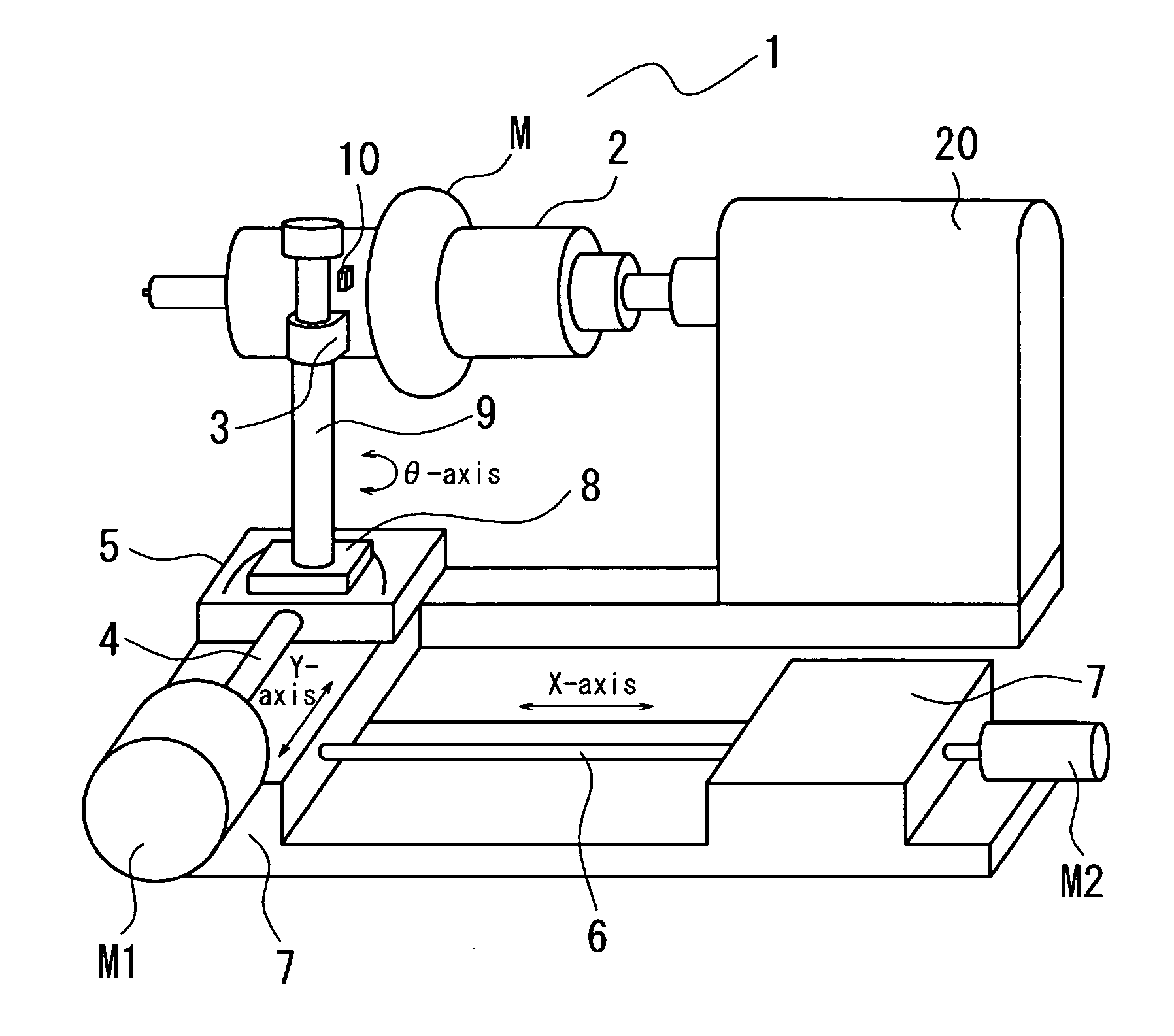
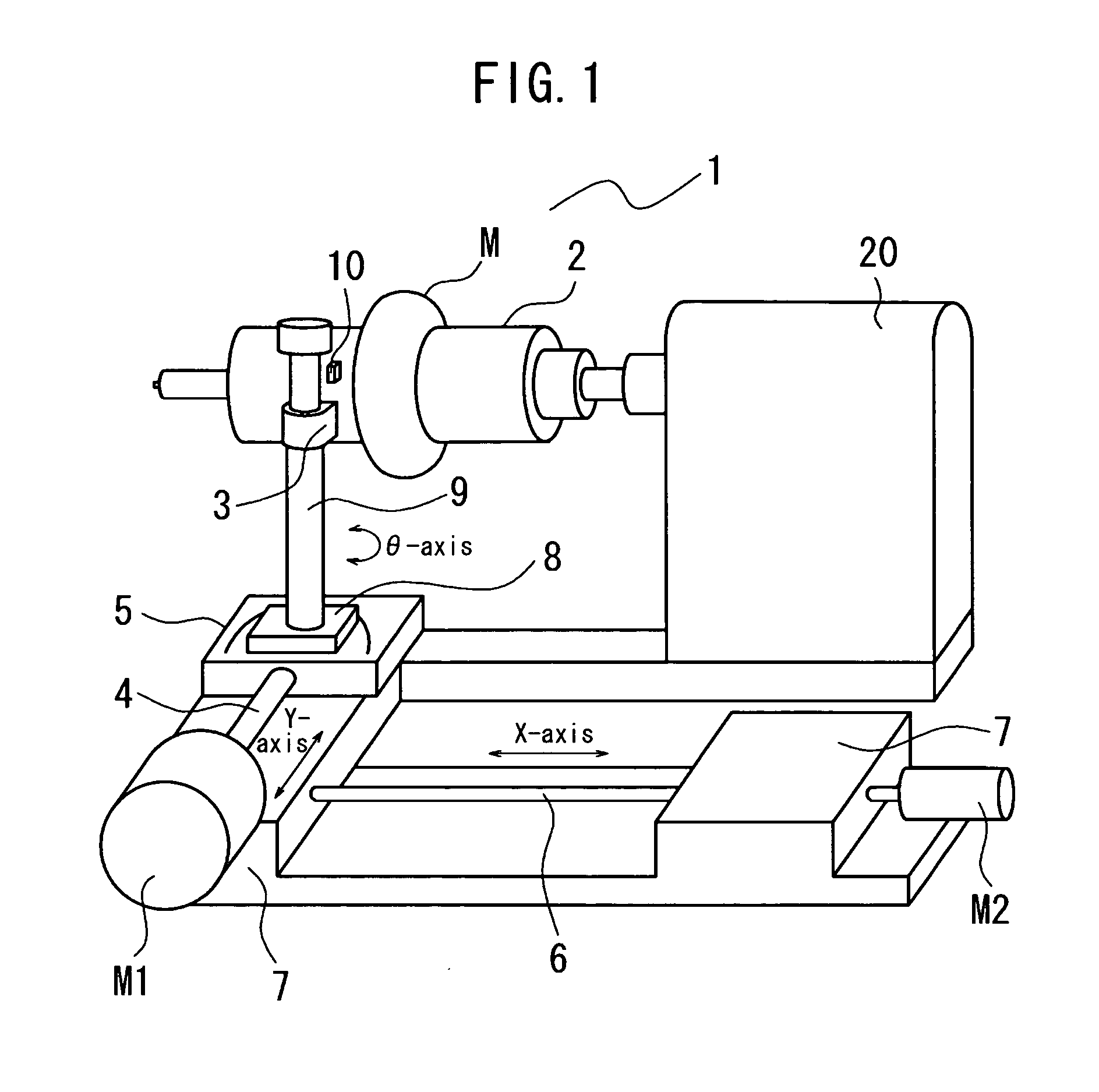
[0037]FIG. 1 is a schematic perspective view of a tire building apparatus having a sensor for measuring a profile of a green tire, according to an embodiment of the present invention.

[0038]A tire building apparatus 1 includes a bonding roller 3, which is an embodiment of a laminating apparatus, for spirally wrapping and laminating a rubber strip M around a building drum 2 consisting of a cylindrical body, which is an embodiment of a building support. The bonding roller 3 is formed as a part of a conventional rubber strip extruder (not shown) having a rubber-strip extruding nozzle.

[0039]The tire building apparatus 1 includes a first movable base 5 that can be moved in a direction toward and away from a building drum 2 (Y-axis direction) by driving means 4 consisting of, for example, a screw rod and a ball screw (a rack and pinion or a cylinder and piston mecha...


PUM

PropertyMeasurementUnit
displacementaaaaaaaaaa
displacement measuringaaaaaaaaaa
surface shapeaaaaaaaaaa

Abstract

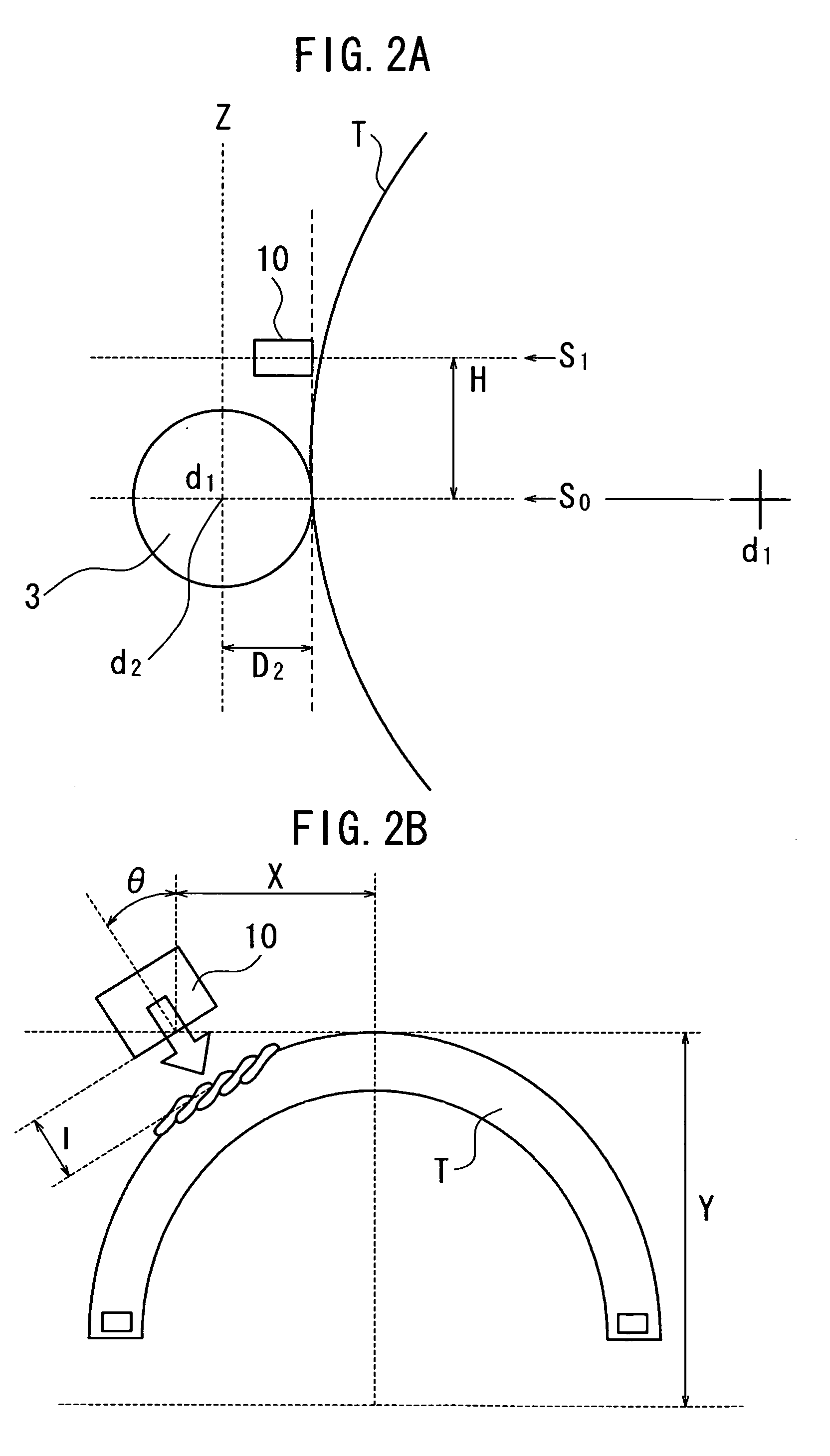
Precise measurement of the entire surface of a green tire is performed during a building process. A laser displacement gauge is provided integrally on a bonding roller for bonding a ribbon to a building drum of a tire building apparatus, and the profile of a green tire after bonding the ribbon is measured while the ribbon is bonded. At this time, the displacement gauge is enabled to move in an X-Y plane and rotate in the same plane to change the orientation while the ribbon is bonded, so as to enable measurement of the entire surface of the tire. Then, the resulting data with respect to the Y-axis direction is corrected according to the difference in position between the bonding roller and the laser displacement gauge.

Description

TECHNICAL FIELD[0001]The present invention relates to a method for measuring a tire in which a profile of a tire built by wrapping a rubber strip is measured in a process of wrapping the rubber strip around a tire building drum, to a tire measuring device, and to a tire building apparatus.BACKGROUND ART[0002]In tire building, an unvulcanized rubber strip continuously fed from an extruder or an injection molding machine is wrapped around a building drum and is bonded by a bonding roller in a layered structure. Thus, tire components are directly formed on the building drum to produce a tire.[0003]In this tire building apparatus, for example, the extruder is mounted on a traverse unit, and, in synchronization with the rotation of the tire building drum, the traverse unit is reciprocated in the width direction thereof. The rubber strip fed from the extruder is wrapped in a predetermined shape by making the extrusion speed of the rubber strip equal to the surface speed of the tire buildi...

Claims


Application Information

Patent Timeline
Patent Type & Authority Applications(United States)
IPC IPC(8): B60C25/00
CPCG01B21/20B29D30/60
Inventor OGAWA, YUICHIRO
Owner BRIDGESTONE CORP
Learn More