Method and apparatus for josephson distributed output amplifier
- Summary
- Abstract
- Description
- Claims
- Application Information
AI Technical Summary
Benefits of technology
Problems solved by technology
Method used
Image

Examples
Embodiment Construction
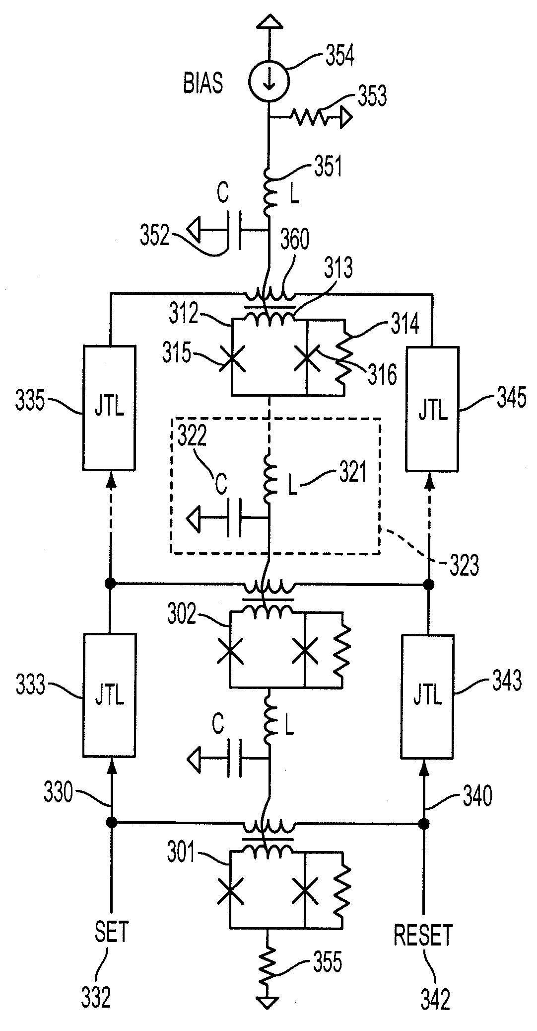
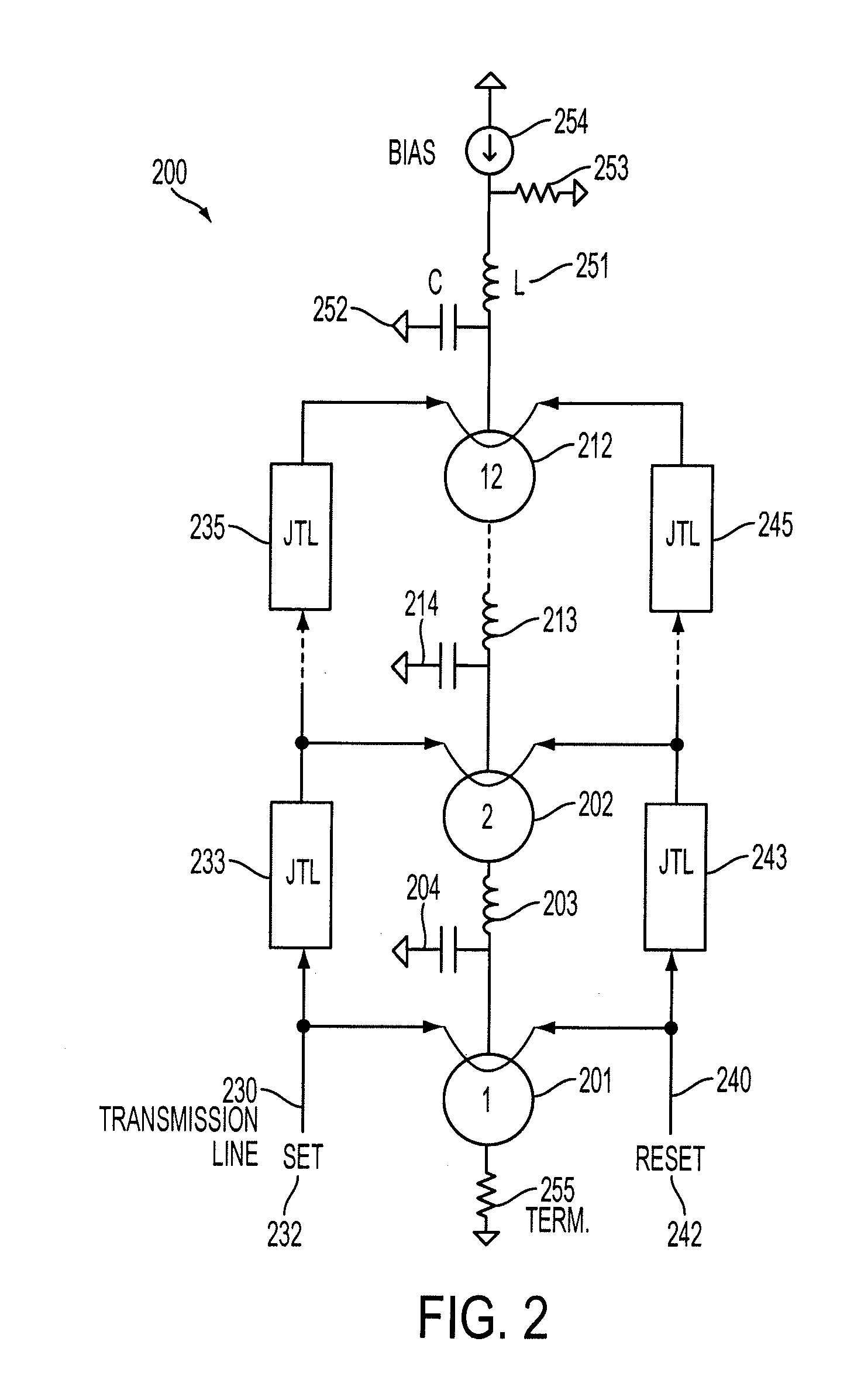
[0018]FIG. 2 schematically illustrates a distributed amplifier according to one embodiment of the disclosure. Circuit 200 of FIG. 2 illustrates a 12 stage amplifier represented by stages 1, 2 . . . 12. For brevity, only stages, 1, 2 and 12 are shown. Each stage is shown as having a voltage source. Thus, the first stage includes voltage source 201; the second stage is shown with voltage source 202. Amplification stage 12 is shown with voltage source 212. Each stage may optionally include a lumped resonant circuit connected to the voltage source. In FIG. 2, voltage source 202 is connected to inductor 203 and capacitor 204. Inductor 203 and capacitor 204 form a lumped resonant circuit. Similarly, voltage source 12 is connected to inductor 213 and capacitor 214.
[0019]FIG. 2 also shows bias 254 connected in parallel with resistor 253. In an exemplary application, termination resistor 255 was matched to resistor 253 and each was provided with 50 Ω resistance. A lumped circuit comprising i...
PUM
 Abstract
Description
Claims
Application Information
 - R&D
- Intellectual Property
- Life Sciences
- Materials
- Tech Scout
- Unparalleled Data Quality
- Higher Quality Content
- 60% Fewer Hallucinations
Browse by: Latest US Patents, China's latest patents, Technical Efficacy Thesaurus, Application Domain, Technology Topic, Popular Technical Reports.
© 2025 PatSnap. All rights reserved.Legal|Privacy policy|Modern Slavery Act Transparency Statement|Sitemap|About US| Contact US: help@patsnap.com