
Method for analyzing superconducting wire

a superconducting wire and analysis method technology, applied in the direction of superconducting magnets/coils, instruments, magnetic bodies, etc., can solve the problem of defective proportion of superconducting wires, and achieve the effect of decreasing the voltage-to-current ratio

Inactive Publication Date: 2010-01-28
AMERICAN SUPERCONDUCTOR
View PDF6 Cites 20 Cited by
  • Summary
  • Abstract
  • Description
  • Claims
  • Application Information

AI Technical Summary

Benefits of technology

[0026]In a fourth implementation of this disclosure, a high temperature superconducting wire is disclosed. The high temperature superconducting wire may include a plurality of portions along its length. At least one of the portions may include a decreasing voltage to current ratio when a voltage / current (VI) test is performed for the portion of the superconducting wire. The VI test may include determining a plurality of VI data points at a first VI datapoint of about (Ic (critical current), Ec (critical electric field)) and at a second VI datapoint of about (Ix, Ex) wherein Ex is approximately equal to at least 10 times Ec and Ix is approximately equal to the current resulting at that voltage drop.
[0027]In a fifth implementation of this disclosure, a high temperature superconducting integrated fault current limiting cable is provided. The high temperature superconducting integrated fault current limiting cable may include a plurality of high temperature superconducting wires. The wires may include a plurality of portions along their lengths and at least one of the wires may include a wire portion with a decreasing voltage to current ratio when a voltage / current (VI) test is performed for the portion of the superconducting wire. The VI test may include determining a plurality of VI data points at a first VI datapoint of about (Ic (critical current), Ec (critical electric field)) and at a second VI datapoint of about (Ix, Ex) wherein Ex is approximately equal to at least 10 times Ec and Ix is approximately equal to the current resulting at that voltage drop.
[0028]The details of one or more implementations are set forth in the accompanying drawings and the description below. Other features and advantages will become apparent from the description, the drawings, and the claims.

Problems solved by technology

A portion of superconducting wire may be deemed defective if the portion of superconducting wire is unacceptable for use in a fault current limiting circuit.

Method used


Image

  • Method for analyzing superconducting wire
  • Method for analyzing superconducting wire
  • Method for analyzing superconducting wire

Examples


Embodiment Construction

Overview

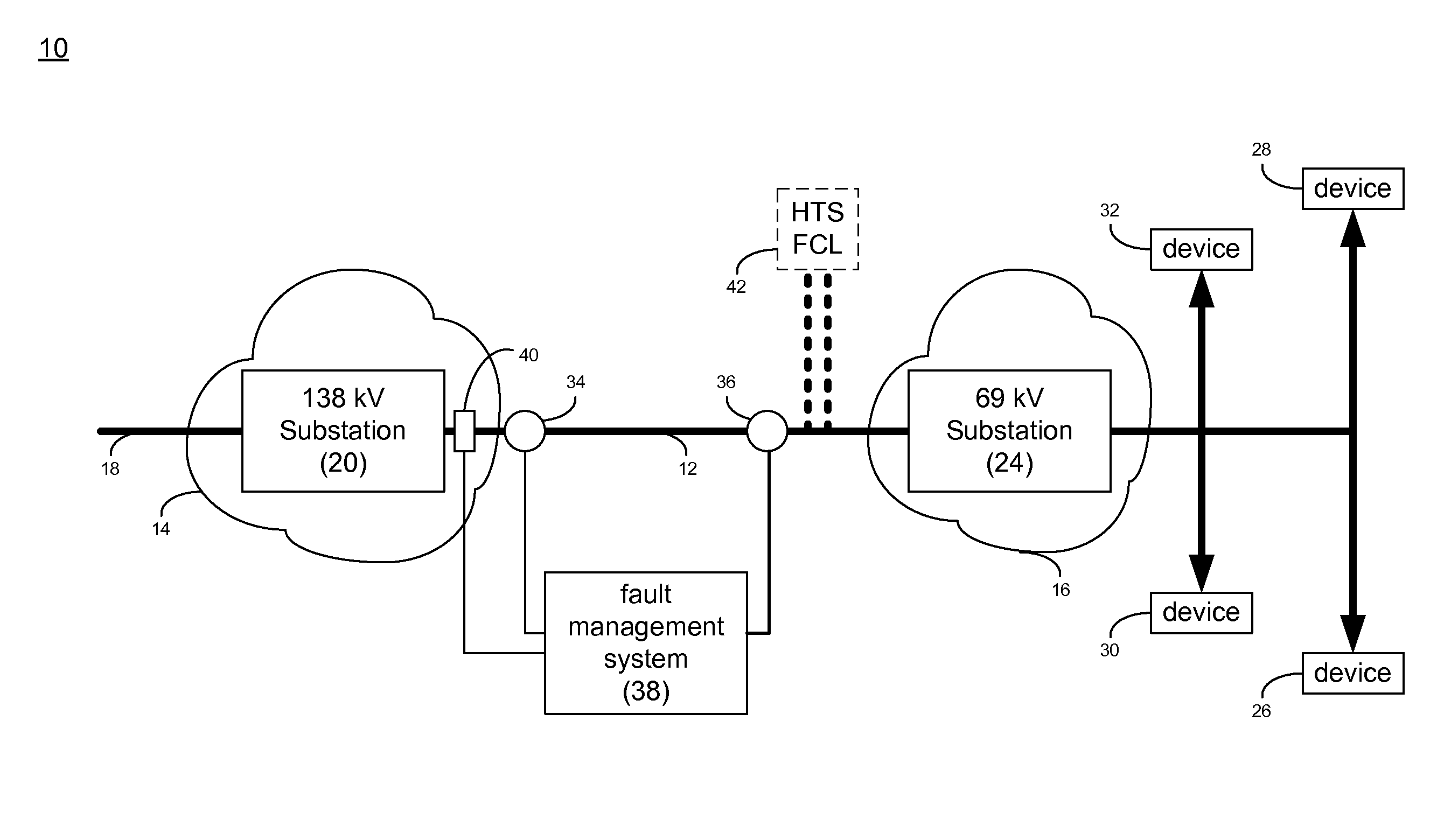
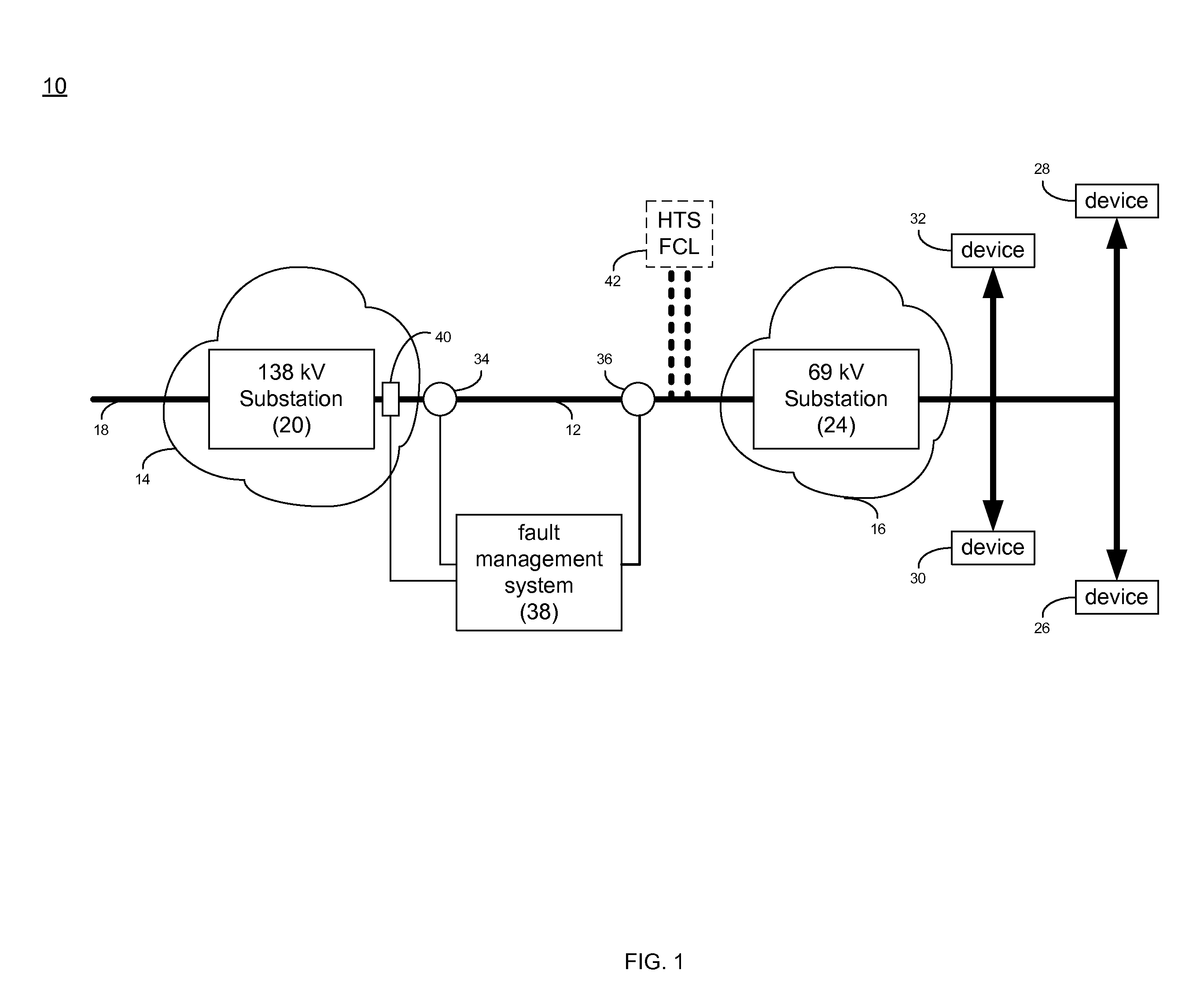
[0046]Referring to FIG. 1, a portion of a utility power grid 10 may include a high temperature superconductor (HTS) cable 12. HTS cable 12 may be hundreds or thousands of meters in length and may provide a relatively high current / low, or essentially zero resistance electrical path for the delivery of electrical power from generation stations (not shown) or imported from remote utilities (not shown).

[0047]The cross-sectional area of HTS cable 12 may only be a fraction of the cross-sectional area of a conventional copper core cable and may be capable of carrying the same amount of electrical current. As discussed above, within the same cross-sectional area, an HTS cable may provide three to five times the current-carrying capacity of a conventional AC cable; and up to ten times the current-carrying capacity of a conventional DC cable. As HTS technology matures, these ratios may increase.

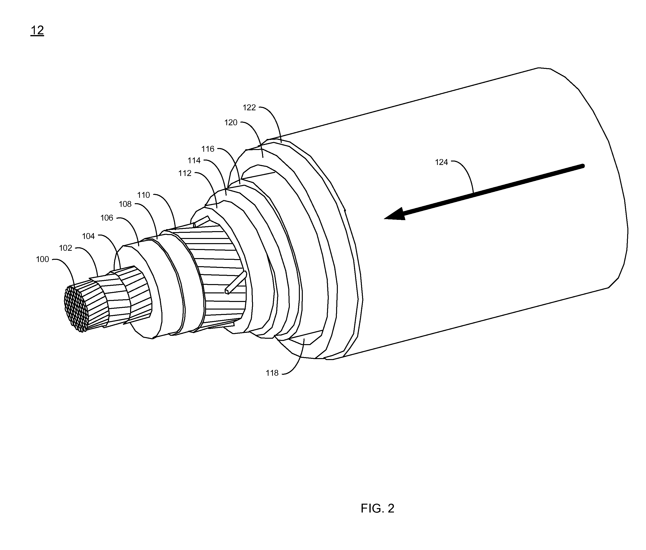
[0048]As will be discussed below in greater detail, HTS cable 12 includes HTS wire, which m...


PUM

PropertyMeasurementUnit
temperatureaaaaaaaaaa
electric fieldaaaaaaaaaa
lengthaaaaaaaaaa

Abstract

The present disclosure relates to a system and method for analyzing a superconducting wire. A method in accordance with at least one embodiment described herein may include performing a voltage / current (VI) test for each of a plurality of portions of superconducting wire. The VI test may include determining a plurality of VI data points for each of the plurality of portions of superconducting wire at a first VI datapoint of about (Ic (critical current), Ec (critical electric field)) and at a second VI datapoint of about (Ix, Ex). Ex may be at least 10 times Ec and Ix may be approximately equal to the current resulting at that voltage drop. The method may further include analyzing the plurality of VI data points for each portion of superconducting wire to determine if one or more of the portions of superconducting wire are defective. Of course, numerous other embodiments are also within the scope of the present disclosure.

Description

GOVERNMENT RIGHTS [0001]This invention was made with Government support under Agreement No.: HSHQDC-08-9-00001. The Government has certain rights in the invention.TECHNICAL FIELD [0002]This disclosure relates to high temperature superconducting (HTS) devices and, more particularly, to a method for testing HTS devices configured to operate as fault current limiting devices.BACKGROUND [0003]As worldwide electric power demands continue to increase significantly, utilities have struggled to meet these increasing demands both from a power generation standpoint as well as from a power delivery standpoint. Delivery of power to users via transmission and distribution networks remains a significant challenge to utilities due to the limited capacity of the existing installed transmission and distribution infrastructure, as well as the limited space available to add additional conventional transmission and distribution lines and cables. This is particularly pertinent in congested urban and met...

Claims


Application Information

Patent Timeline
Patent Type & Authority Applications(United States)
IPC IPC(8): G01R31/02H01B12/02
CPCG01R33/1246G01R31/022G01R31/59
Inventor FOLTS, DOUGLAS C.PODTBURG, ERIC R.DIEHL, ROBERT C.
Owner AMERICAN SUPERCONDUCTOR
Learn More