
Wireless charging system

a charging system and wireless technology, applied in the field of wireless power supply systems, can solve the problems of increasing concerns about the problems associated with conventional battery chargers, unfavorable operation, and unsightly cords of conventional corded battery chargers, and achieve the effects of reducing the number of wires

Active Publication Date: 2010-01-14
PHILIPS IP VENTURES BV
View PDF85 Cites 470 Cited by
  • Summary
  • Abstract
  • Description
  • Claims
  • Application Information

AI Technical Summary

Benefits of technology

[0004]To overcome these and other problems associated with corded battery chargers, there is a growing trend toward the use of wireless charging systems for charging batteries in portable electronic devices. Wireless charging systems offer a number of advantages. For example, they eliminate the unsightly mess created by a collection of charger cords and eliminate the need for users to plug and unplug the device from the charger.
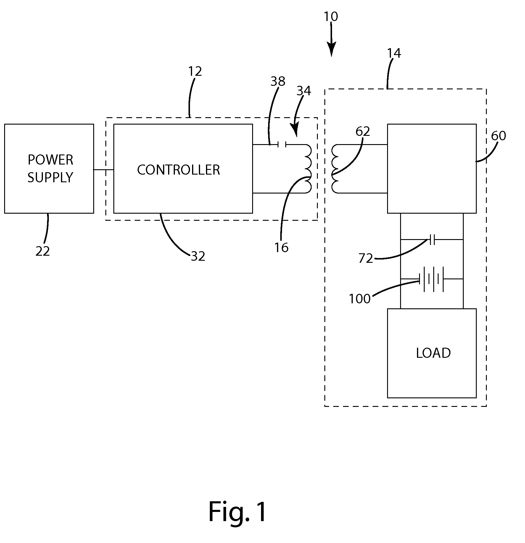
[0006]The present invention provides a battery-operated remote control with a wireless charging system having an inductive power supply and a secondary power circuit with a charge storage capacitor and a charging subcircuit for charging the battery with the power stored in the charge storage capacitor. In operation, the secondary power circuit wirelessly receives power from the inductive power supply and rapidly charges the capacitor. The charging subcircuit charges the battery with the power from the charge storage capacitor at a rate appropriate for battery charging. Because power is stored in the capacitor, battery charging can continue even after the remote control is removed from the inductive power supply.
[0009]In one embodiment, the secondary includes a charging circuit connecting the capacitor and the battery. The charging circuit may be nothing more than an electrical connector that connects the battery and the capacitor. Alternatively, the charging circuit may be a more complicated charging circuit, such as an appropriate diode to prevent the battery from leaking power into the capacitor or a charge control circuit incorporated into an integrated circuit.
[0013]The present invention provides a simple and effective wireless recharging system suitable for remote control systems and other battery-operated electronic devices. Because the charge storage capacitor charges much more quickly than a conventional rechargeable battery, the charge storage capacitor can be much more rapidly charged than the battery. As a result, the present invention allows the secondary power circuit to quickly store sufficient power to operate the electronic device for at least a short period. Further, the communication system allows the inductive power supply to adapt its operating parameters, such as operating frequency and / or duty cycle, to provide efficient operation. Additionally, the communication system facilitates interoperability by permitting compatible remote devices to identify themselves to the inductive power supply and to initiate inductive charging.

Problems solved by technology

With continued growth in the use of battery-operated portable electronic devices, there are increasing concerns about the problems associated with conventional battery chargers.
The design of the battery charger, including power specifications and plug configuration, typically varies from device to device such that a battery charger of one device is not likely to operate properly in charging the batteries of another device.
The cords of conventional corded battery chargers are unsightly and have a tendency to become tangled both alone and with cords of other chargers.
Corded chargers are also relatively inconvenient because a user is required to plug and unplug the cord each time the device is charged.
Although wireless charging systems can be a marked improvement over wired chargers, they continue to suffer from some inconveniences.
For example, due to limitations inherent in their nature of batteries, conventional battery chargers charge at a relatively slow rate.
As a result, a device that has exhausted its battery must remain on the charger for a relatively long period before it is capable of further use.
The inability to use a device for an extended period while it remains on the charger can be a significant inconvenience.

Method used


Image

  • Wireless charging system
  • Wireless charging system
  • Wireless charging system

Examples


Embodiment Construction

[0029]I. Overview.

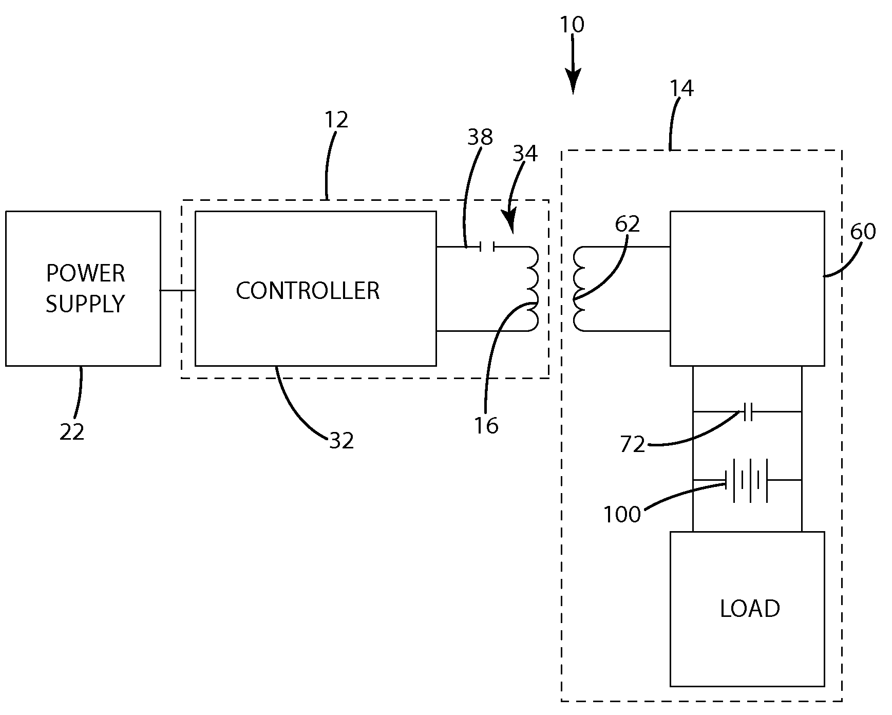
[0030]A remote control system 10 having an inductive charging system in accordance with an embodiment of the present invention is shown in FIG. 1. The system generally includes an inductive power supply 12 and a battery-operated remote control 14. The inductive power supply 12 generates an electromagnetic field capable of wirelessly transmitting power to the remote control 14. The remote control 14 includes a secondary power supply circuit 60 capable of receiving power and delivering it in a usable form when in the presence of an appropriate electromagnetic field. The power induced in the secondary circuit 60 is rapidly stored in a charge storage capacitor 72. The power stored in the charge storage capacitor 72 is used to charge the battery 100 over an extended timeframe suitable for battery charging. Accordingly, power can be quickly stored in the charge storage capacitor 72 and used to continue to charge the battery 100 even after the remote control 14 is removed...


PUM


Abstract

The present invention provides wireless power supply systems that wirelessly supply power to a remote device for rapidly charging a charge storage capacitor, which charges a battery with the power stored in the charge storage capacitor. This allows the remote device to be positioned near the inductive power supply for rapid charging of the charge storage capacitor and allows battery charging to continue even after the remote device is removed from the inductive power supply.

Description

BACKGROUND OF THE INVENTION[0001]This application claims the benefit of U.S. Provisional Patent Application 61 / 079,301 filed on Jul. 9, 2008, which is herein incorporated by reference in its entirety.[0002]The present invention relates to wireless power supply systems, and more particularly to a system for wirelessly charging an electronic device.[0003]With continued growth in the use of battery-operated portable electronic devices, there are increasing concerns about the problems associated with conventional battery chargers. Battery-operated portable electronic devices are often provided with a battery charger for use in recharging the batteries. Many conventional battery chargers include a power cord that plugs into a power input port on an electronic device. The design of the battery charger, including power specifications and plug configuration, typically varies from device to device such that a battery charger of one device is not likely to operate properly in charging the bat...

Claims


Application Information

Patent Timeline
IPC IPC(8): H02J7/00
CPCH02J7/025H02J5/005H02J50/10H02J50/12H02J50/80H02J7/00034H02J50/90H02J50/70H04B5/79
Inventor BAARMAN, DAVID W.NGUYEN, HAI D.TAYLOR, JOSHUA B.SCHWANNECKE, JOSHUA K.NORCONK, MATTHEW J.
Owner PHILIPS IP VENTURES BV
Learn More