Tapered roller bearing
a tapered roller bearing and roller bearing technology, applied in the direction of rolling contact bearings, shafts and bearings, rotary bearings, etc., can solve the problems of insufficient prior tapered roller bearing technology to cope with such severe conditions, and not being absolutely satisfactory for high speed rotation, so as to reduce the deflection of the end face of the large end face, reduce the factor which inhibits oil film formation, and reduce the effect of contact pressure variations
- Summary
- Abstract
- Description
- Claims
- Application Information
AI Technical Summary
Benefits of technology
Problems solved by technology
Method used
Image

Examples
first embodiment
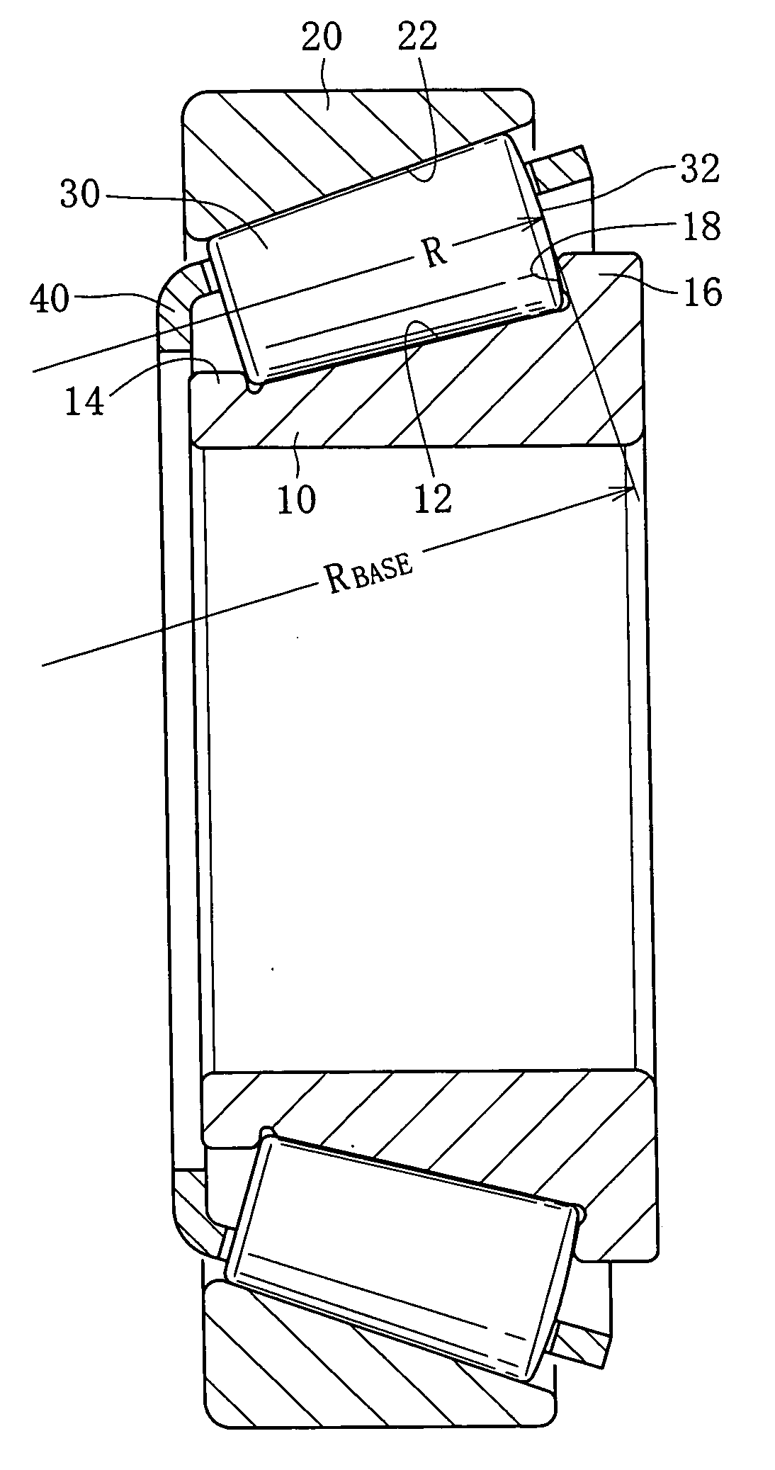
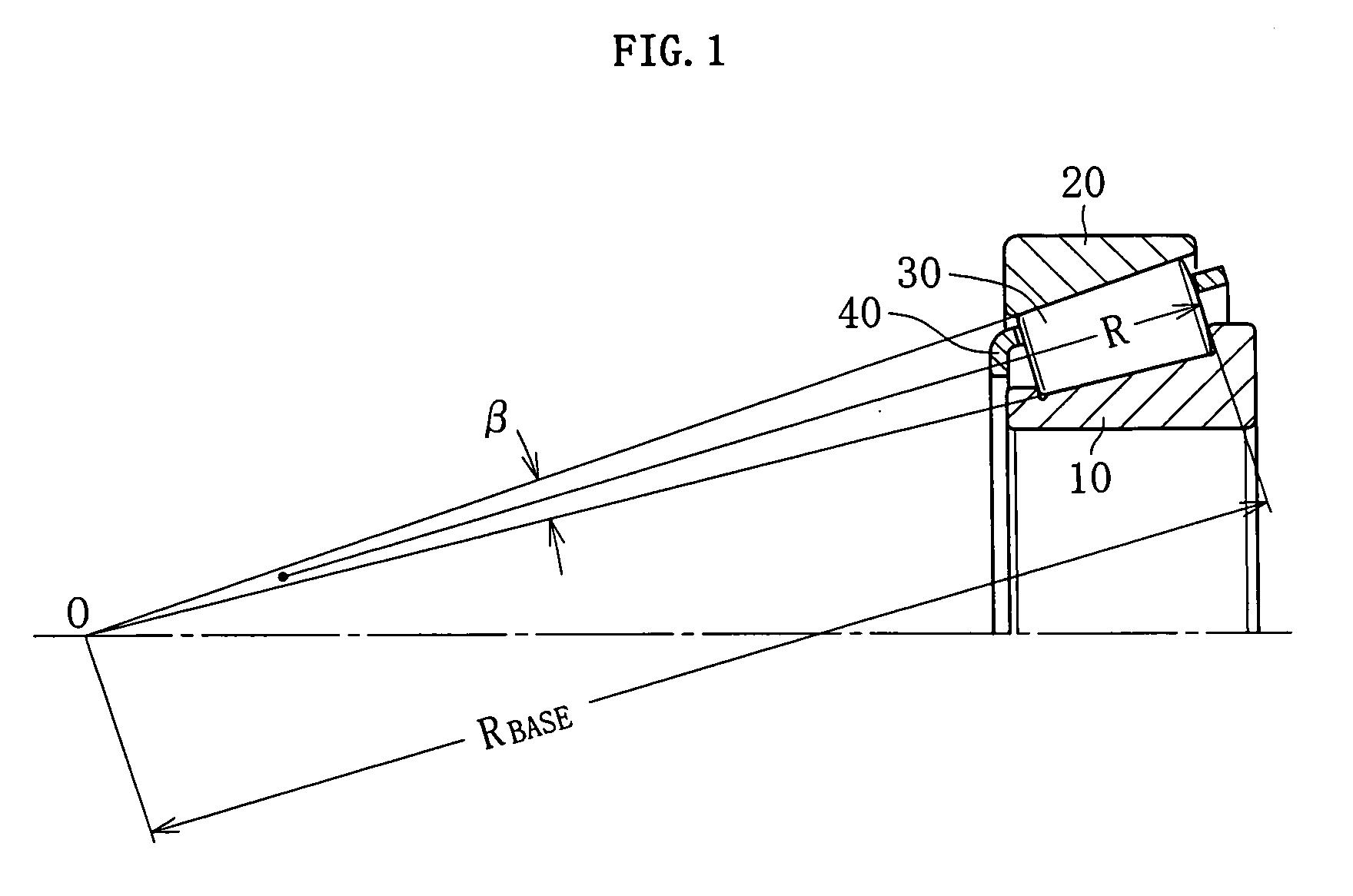
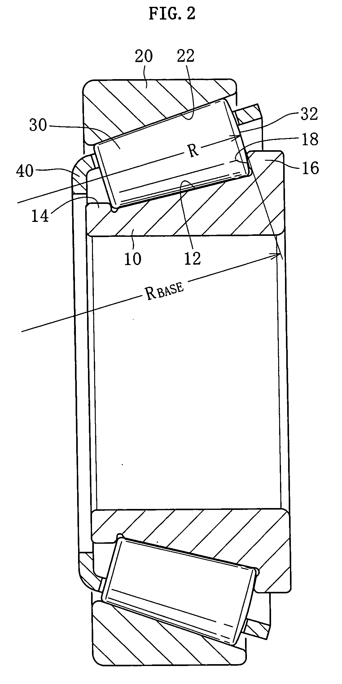
[0038]As shown in FIGS. 1 and 2, a tapered roller bearing is composed of an inner ring 10, an outer ring 20, tapered rollers 30, and a cage 40. The inner ring 10 has a tapered roller-like raceway 12 in its outer periphery and is provided with a cone front face rib 14 and a cone back face rib 16 on opposite sides of the raceway 12. The character 18 denotes the surface of the inner ring 10 in contact with the cone back face rib surface, i.e., the large end face 32 of the tapered roller 30. The outer ring 20 has a tapered roller-like raceway 22 in its inner periphery. The tapered rollers 30 are rollably interposed between the raceways 12 and 22 of the inner and outer rings 10 and 20. The cage 40 has a plurality of pockets circumferentially disposed at predetermined circumferential intervals, with each pocket having a tapered roller 30 received therein.
[0039]The tapered rollers 30 are in linear contact with the raceways 12 and 22 of the inner and outer rings 10 and 20, the design being ...
second embodiment
[0056]A description will be given of the second embodiment of the invention corresponding to a modification of the first embodiment described above.
[0057]Tapered roller bearings are bearings suitable for being loaded with radial load and axial load and combined load consisting thereof and have a large load capacity. Therefore, in power transmission devices such as differentials and transmissions of vehicles such as automobiles and construction machines, use is made of support devices which support gear shafts by tapered roller bearings. Transmissions for automobiles are classified broadly into the manual type and the automatic type. Further, they can also be classified according to the driving system of the vehicle: a trans-axle for front wheel drive (FWD), a transmission for rear wheel drive (RWD), and a transfer (auxiliary speed changing unit) for four-wheel drive (4WD). They are used to speed-change the drive power from the engine and to transmit it to the drive shaft or the like...
example 1
[0096]Example 1 of the invention was made by using JIS SUJ2 Material (1.0 wt % C—0.25 wt % Si—0.4 wt % Mn—1.5 wt % Cr). Table 2 shows the production histories of the samples.
TABLE 2ConventionalNormalSamplecarbonitridedhardenedABCDEFarticlearticleSecondary7801)800815830850870——hardeningTemperature(□)Hydrogen—0.370.400.380.420.400.720.38quantity(ppm)Crystal—1211.51110101010grain size(JIS)Charpy—6.656.406.306.206.305.336.70impactvalue(J / cm2)Breaking—2840278026502650270023302770stressvalue(MPa)Rolling—5.44.23.52.92.83.11fatiguelifeRatio (L10)1)This time, insufficient hardening made evaluation impossible.
[0097](Samples A-D: Inventive Examples)
[0098]Carbonitriding treatment was performed: carbonitriding temperature, 850□, holding time, 150 minutes. The atmosphere at the time of carbonitriding treatment was a gas mixture of RX gas and ammonia gas. In the heat treatment pattern shown in FIG. 11, primary hardening was performed at a carbonitriding temperature of 850□ and the samples were hea...
PUM
 Abstract
Description
Claims
Application Information
 - R&D
- Intellectual Property
- Life Sciences
- Materials
- Tech Scout
- Unparalleled Data Quality
- Higher Quality Content
- 60% Fewer Hallucinations
Browse by: Latest US Patents, China's latest patents, Technical Efficacy Thesaurus, Application Domain, Technology Topic, Popular Technical Reports.
© 2025 PatSnap. All rights reserved.Legal|Privacy policy|Modern Slavery Act Transparency Statement|Sitemap|About US| Contact US: help@patsnap.com