
Toric intraocular lens with modified power characteristics

a technology of power characteristics and intraocular lens, applied in the field of intraocular lens, can solve the problems of degrading the vision of the eye, inability to correct, and difficulty in equal-but-opposite astigmatism correction

Active Publication Date: 2009-12-31
ABBOTT MEDICAL OPTICS INC
View PDF4 Cites 141 Cited by
  • Summary
  • Abstract
  • Description
  • Claims
  • Application Information

AI Technical Summary

Benefits of technology

"The patent describes a type of ophthalmic lens that has meridians associated with it, including a high power meridian and a low power meridian. The lens has a radially modulated meridian along which power varies with increasing radial position. This results in non-constant power along at least one meridian. The patent also describes a method of manufacturing the lens by applying a modification function to a standard toric lens function to obtain the modified toric lens function. The technical effect of this patent is to provide a toric ophthalmic lens with improved optical performance and a more natural feel for the wearer."

Problems solved by technology

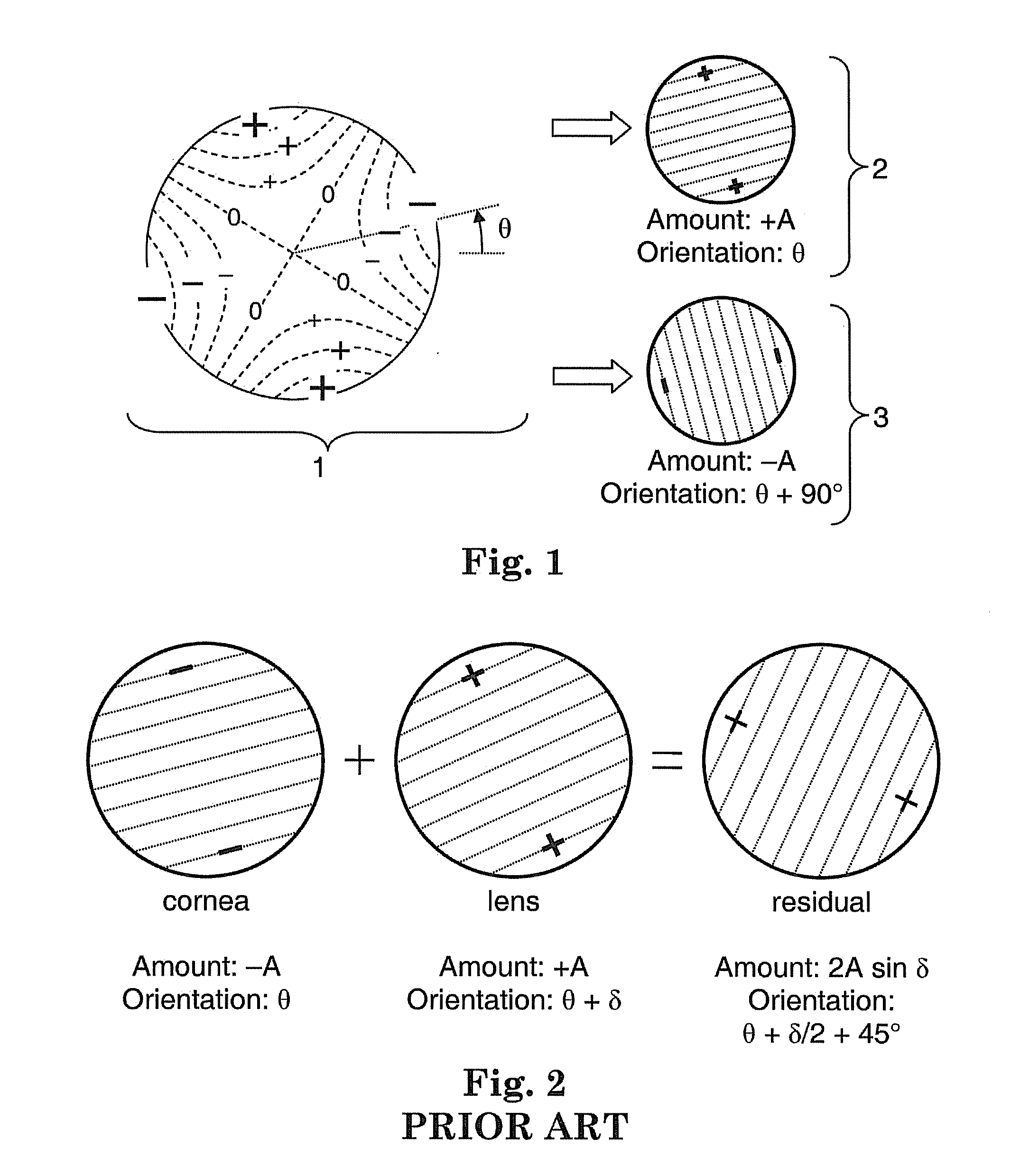
The astigmatism degrades the vision of the eye, and cannot be corrected by adjusting the power of the lens.
In practice, there are difficulties with an equal-but-opposite astigmatism correction.
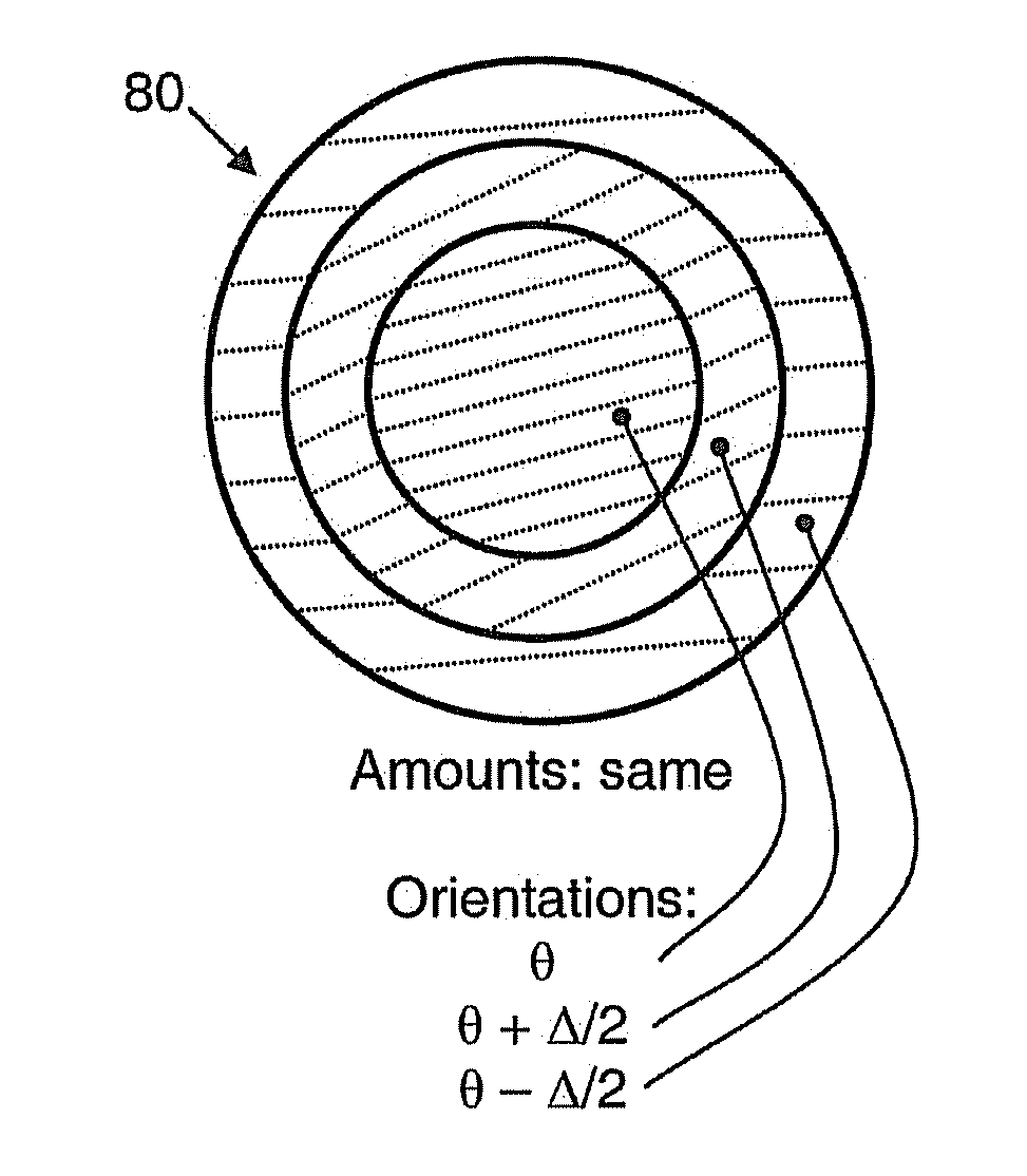
However, there is usually a small angular error in the orientation that arises during the implantation surgery, which is denoted in FIG. 2 as δ, so that the astigmatism of the lens is oriented at angle θ+δ after implantation.
This angular error may be kept as small as possible, but may be limited in practice by the skill of the surgeon.
While more skilled surgeons may be able to achieve a δ of about 5 degrees, less skilled surgeons may have difficulty meeting this value and may implant lenses with larger angular errors than 5 degrees.
As a result, the residual astigmatism in the eye may impose a prohibitively tight tolerance on the angular orientation of the lens during implantation, resulting in a tedious and expensive implantation procedure.

Method used


Image

  • Toric intraocular lens with modified power characteristics
  • Toric intraocular lens with modified power characteristics
  • Toric intraocular lens with modified power characteristics

Examples


first example

[0095]FIG. 18 is a graph that depicts power versus radial position (along a meridian) for a first embodiment of a toric lens having radially modulated characteristics. FIG. 19 is a schematic drawing of an optical element or lens 200 having a clear aperture 201 and the power characteristics depicted in FIG. 18 (as used herein, the term “clear aperture” means the opening of a lens or optic that restricts the extent of a bundle of rays from a collimated source or a distant light source that can imaged or focused by the lens or optic). In FIG. 19, the horizontal axis represents the low power meridian (labeled “L”) and the vertical axis represents the high power meridian (labeled “H”). For this example, r0 is the originating position (which has a value of zero in the illustrated embodiment), r1 is the radial position that defines a central zone 202, r2 is the radial position that defines the outer boundary of an intermediate zone 204, and r3 is the radial position that defines the outer ...

second example

[0103]The plots in FIG. 18 define the nominal power PN in the central zone 202, the overcorrecting power POC in the intermediate zone 204, and the undercorrecting power PUC in the outer zone 206. In contrast, FIG. 20 is a graph that depicts power versus radial position (along one meridian) for a different embodiment of a radially modified toric lens. Here, the central zone (between r0 and r1) has an overcorrecting lens power, the intermediate zone (between r1 and r2) has the nominal lens power, and the outer zone (between r2 and r3) has an undercorrecting lens power. As mentioned above with reference to FIG. 18, the general characteristic of the plot in FIG. 20 may be followed by some or all of the meridians of the optical element. Moreover, the values of POC, PN, and PUC may vary with the meridian angle θ according to any of the embodiments described above in relation to FIGS. 18 and 19. For example, the power along the low power meridian 217, or one or more other meridians, may co...

third example

[0104]FIG. 21 is a graph that depicts power versus radius for a toric lens, where the power monotonically decreases in a stepwise manner. The power characteristic depicted in FIG. 21 may be realized using a toric lens having five annular zones that are defined by the five radii (labeled r1 to r5 in FIG. 21). In practice, the number of steps and the height of each step will be chosen to best suit the needs of the given patient or class of patient. In certain embodiments, the power along one or more meridians may decrease in a continuous manner in one zone and decrease in stepwise manner in another zone. In other words, the modification scheme may result in a “hybrid” approach that combines continuous and stepwise transitions along a given meridian. The values of POC, PN, and PUC may vary with the meridian angle θ in an absolute or relative sense according to any of the embodiments described above in relation to FIGS. 18 and 19. In some embodiments, the power POC in FIG. 21 along a hi...


PUM


Abstract

An intraocular lens for correcting or reducing the astigmatism of a cornea includes an optical element that has optical properties and characteristics that make it tolerant of rotational misalignment, when compared to a comparable lens having a uniform astigmatism orientation across its entire optical element, leading to more relaxed tolerances for a surgeon that implants the lens. The optical element of the toric ophthalmic lens has meridians associated therewith, including a high power meridian and a low power meridian orthogonal to the high power meridian. The optical element has at least one radially modulated meridian along which power monotonically varies with increasing radial position.

Description

RELATED APPLICATION[0001]This application is a continuation-in-part application of, and claims priority to, U.S. patent application Ser. No. 12 / 035,370, filed Feb. 21, 2008, and to U.S. provisional application No. 61 / 185,911, filed on Jun. 1, 2009, the entire contents of each of which applications are hereby incorporated by reference in their entirety for all purposes as if fully set forth herein.TECHNICAL FIELD[0002]The subject matter described herein relates generally to an intraocular lens, and more specifically to an intraocular lens having variable power along its meridians.BACKGROUND[0003]There are many medical conditions that degrade the vision of a patient's eye. For instance, cataracts can cause the natural lens of an eye to become opaque. Fortunately, in many of these cases, the natural lens of the eye may be removed surgically and replaced with an intraocular lens, thereby restoring the vision of the eye.[0004]Typically, the power required of the intraocular lens is deter...

Claims


Application Information

Patent Timeline
Patent Type & Authority Applications(United States)
IPC IPC(8): G02C7/06A61F2/16
CPCA61F2/1613G02C7/028G02C7/04G02C7/042G02C7/045G02C2202/02G02C2202/20G02C7/027G02C7/044A61F2/1645A61F2/1654A61F2250/0053
Inventor ZHAO, HUAWEIWEEBER, HENDRIK A.PIERS, PATRICIA ANN
Owner ABBOTT MEDICAL OPTICS INC
Learn More