Spatial multiplexing gain for a distributed cooperative communications system using randomized coding

a distributed cooperative communication and spatial multiplexing technology, applied in the field of wireless communication, can solve the problems of limiting the number of antennas integrated on portable devices, limiting the possible gains of existing mimo systems, and distributing the foregoing information could become impractical, so as to loosen the requirements of synchronization and network topology. , the effect of high spatial multiplexing gain

Inactive Publication Date: 2009-12-24
POLYTECHNIC INSTITUTE OF NEW YORK UNIVERSITY
View PDF3 Cites 50 Cited by
  • Summary
  • Abstract
  • Description
  • Claims
  • Application Information

AI Technical Summary

Benefits of technology

[0019]Exemplary embodiments consistent with the present invention allow multiple cooperative relays to operate in a highly mobile environment and form a virtual antenna array. Multiple independent streams of data can be simultaneously transmitted in parallel to the destination receiver. Thus a higher spatial multiplexing gain can be obtained. Such exemplary embodiments might do so by allowing each relay to transmit a linear combination of antenna waveforms according to an independently and randomly generated coefficient vector. Thus, for example, rather than requiring coordination (and the signaling necessary for such coordination) among relays such that each only transmits an pre-assigned portion of the stream, each relay may independently transmit (an independently and randomly selected) part of each portion of the stream. This loosens requirements on synchronization and network topology while providing a virtual MIMO broadband physical layer.

Problems solved by technology

Unfortunately, however, due to the limited size of the portable devices, there is a practical limitation on the number of antennas integrated on portable devices.
This limits the possible gains for existing MIMO systems.
Although the wireless medium allows nodes to overhear other transmissions, traditional wireless networks ignore this overheard information (and may consider it to be unwanted interference).
Unfortunately, network changes (e.g., due to a relay entering or leaving the system, or the loss or degradation of a channel between relay and a source or destination) need to be signaled, and distributing the foregoing information could become impractical.
Mobility, channel fading and the large number of nodes in a typical wireless network make it very costly, if not impossible, to distribute such information with minimal overhead within the channel coherence time (that is, the time period over which the signal strength information is valid).
Third, if information on global channel conditions is not available, relay selection and code allocation has to be based on information that is likely outdated.
However due to variations in the channel, the pre-determined error rate thresholds at the chosen relays may not be met resulting in severe loss in performance.
Fourth, even though nodes other than the chosen relays may decode the source information correctly, they are not allowed to transmit (since a specific channel is transmitted to a specific, assigned, relay).
This sacrifices the diversity and coding gains of BLAST.
Fifth, a distributed BLAST system would have tight constraints on the time synchronization of the nodes, putting a very heavy (if not unrealistic) burden on the MAC (layer 2—data link) and PHY (layer 1—physical) layers.
Sixth, each individual wireless link is not necessarily reliable.
In a distributed BLAST system, even if only one of the relays fails to receive the data sent from the source device, one stream of the data is lost, and the destination receiver would be unable to decode the packet.

Method used


Image

  • Spatial multiplexing gain for a distributed cooperative communications system using randomized coding
  • Spatial multiplexing gain for a distributed cooperative communications system using randomized coding
  • Spatial multiplexing gain for a distributed cooperative communications system using randomized coding

Examples


Embodiment Construction

[0026]In a traditional MIMO system, each antenna can transmit an independent information stream to provide multiplexing gain (See, e.g., L. Zheng and D. N. C. Tse, “Diversity and Multiplexing: A Fundamental Tradeoff In Multiple-Antenna Channels,”IEEE Trans. on Info. Theory, Vol. 49, No. 5, pp. 1073-1096 (October 2003) (incorporated herein by reference).), as done in BLAST. In BLAST, at least as many receive antennas as transmit antennas, as well as a rich scattering environment, are needed to be able to distinguish the information streams.

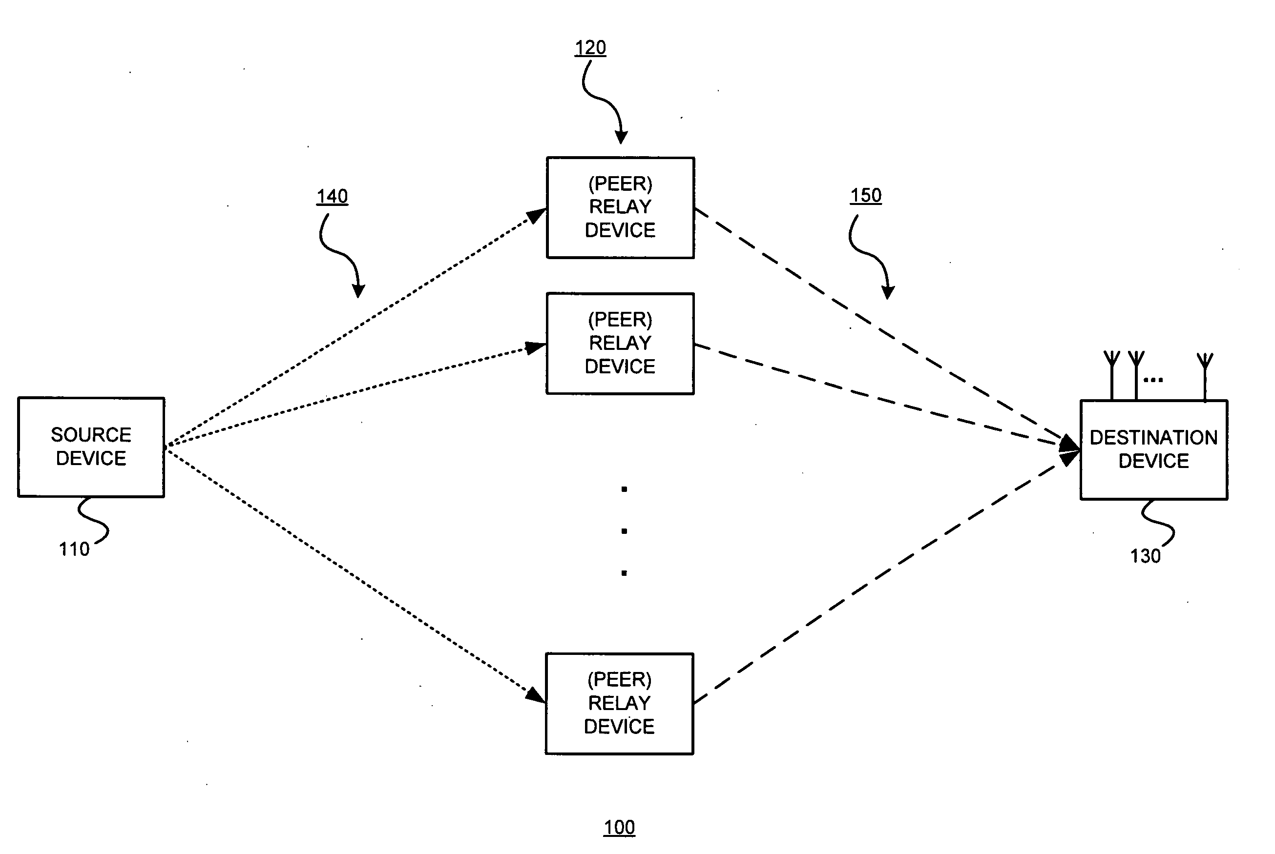
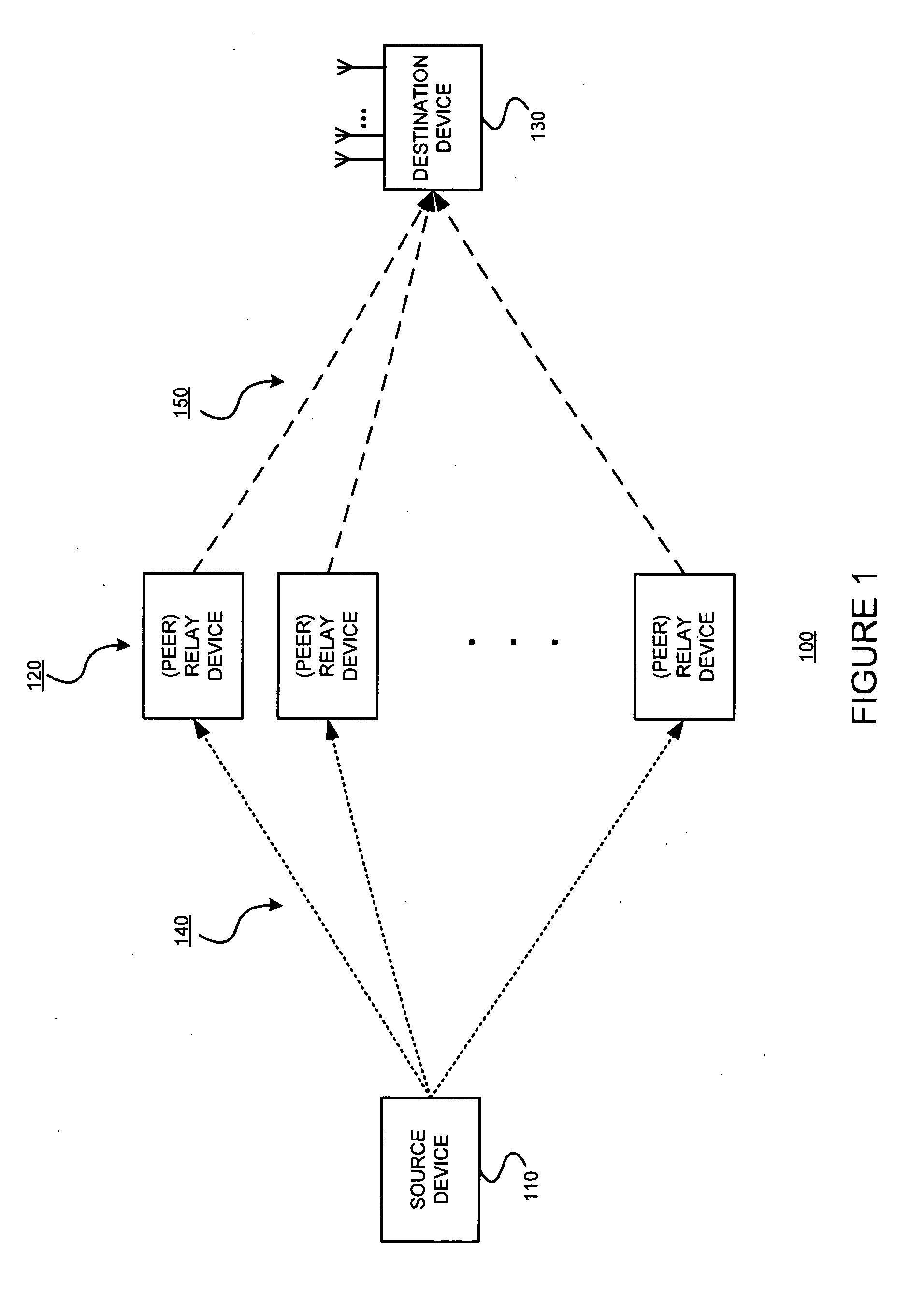
[0027]Embodiments consistent with the present invention apply randomization to mimic BLAST in a distributed system, and exploit the spatial multiplexing gain provided by the relay devices. This is done in a distributed way and can obtain much higher throughput than the single relay cooperative transmission scheme.

[0028]This randomized cooperation scheme may be useful in an environment in which a group of relay devices are close to the source device...


PUM


Abstract

Multiple cooperative relays operate in a highly mobile environment and form a virtual antenna array. Multiple independent streams of data can be simultaneously transmitted in parallel to the destination receiver. Thus a higher spatial multiplexing gain can be obtained. Such exemplary embodiments might do so by allowing each relay to transmit a linear combination of antenna waveforms according to an independently and randomly generated coefficient vector. This randomized cooperation scheme may be useful in an environment in which a group of relay devices are close to the source device, and can therefore receive information at a high rate. Each relay device that receives the information without errors splits it into multiple streams. For example, if the relay devices receive B symbols and the number of streams is K, each stream contains B / K symbols. Each relay device then generates a random linear combination of all the streams and transmits this output simultaneously with the other relay devices.

Description

§ 0.1 RELATED APPLICATIONS[0001]Benefit is claimed to the filing date of U.S. Provisional Patent Application Ser. No. 61 / 058,721 (“the '721 provisional”), titled “SPATIAL MULTIPLEXING GAIN FOR A DISTRIBUTED COOPERATIVE COMMUNICATIONS SYSTEM USING RANDOMIZED CODING,” filed on Jun. 4, 2008 and listing Elza ERKIP, Thanasis KORAKIS, Pei LIU, and Shivendra S. PANWAR as inventors. The '721 provisional is incorporated herein by reference. However, the scope of the claimed invention is not limited by any requirements of any specific embodiments described in the '721 provisional.§ 0.0 GOVERNMENT RIGHTS[0002]The United States Government may have certain rights in this invention pursuant to a grant awarded by the National Science Foundation. Specifically, the United States Government may have a paid-up license in this invention and the right in limited circumstances to require the patent owner to license others on reasonable terms as provided for by the terms of Contract or Grant No. Award No....

Claims


Application Information

Patent Timeline
Patent Type & Authority Applications(United States)
IPC IPC(8): H04L25/20
CPCH04L2025/03426H04L25/20H04B7/15592
Inventor ERKIP, ELZAKORAKIS, THANASICLIU, PEIPANWAR, SHIVENDRA S.
Owner POLYTECHNIC INSTITUTE OF NEW YORK UNIVERSITY
Why Eureka
Try Eureka