
Power consumption feedback systems

a technology of power consumption and feedback system, applied in the direction of electric digital data processing, electric vehicles, instruments, etc., can solve the problems of large expense, difficult access to locations, and employing specialist staff, and achieve the effect of improving accuracy and energy efficiency

Inactive Publication Date: 2009-12-17
ALERTME COM
View PDF6 Cites 96 Cited by
  • Summary
  • Abstract
  • Description
  • Claims
  • Application Information

AI Technical Summary

Benefits of technology

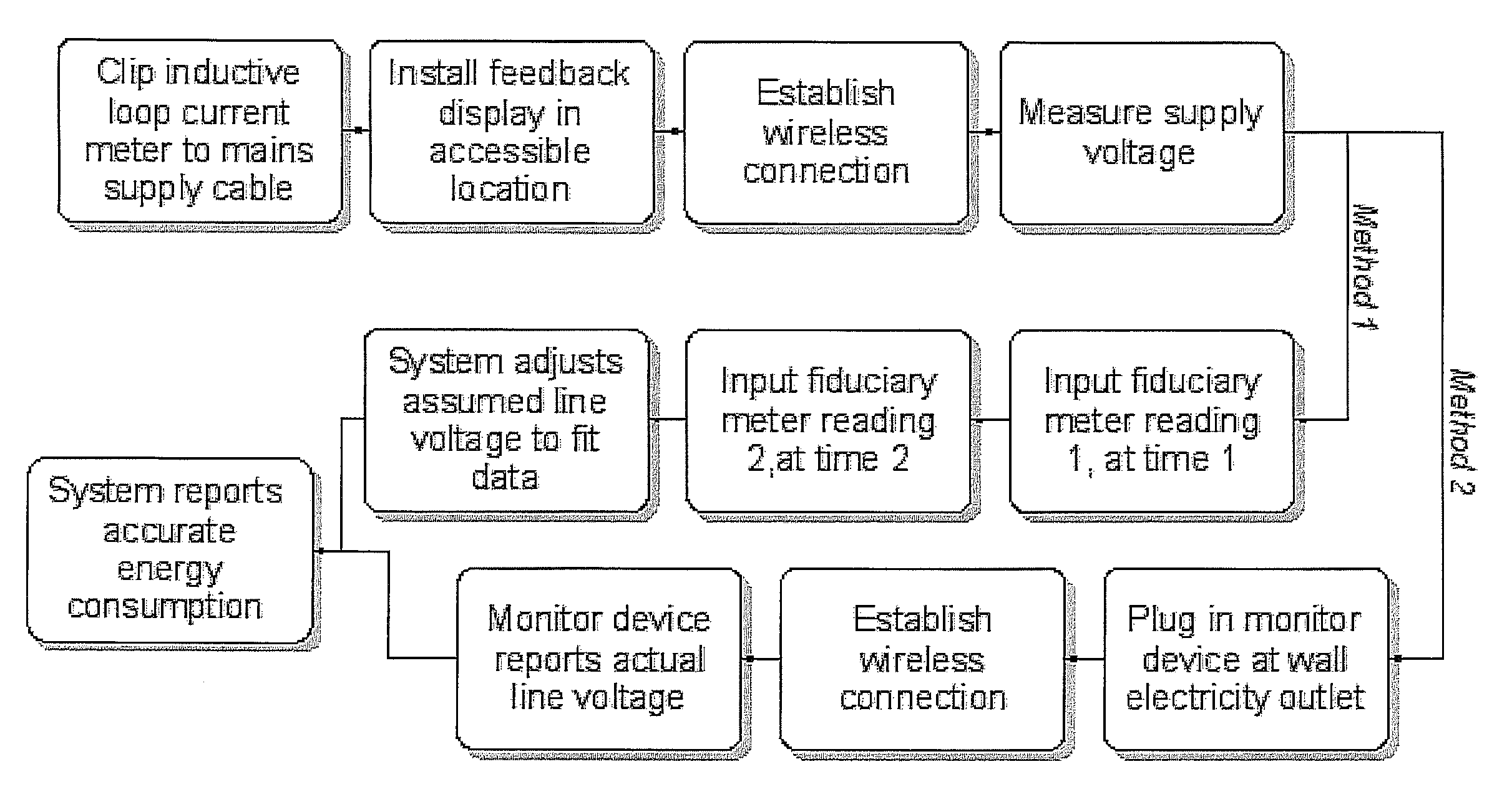
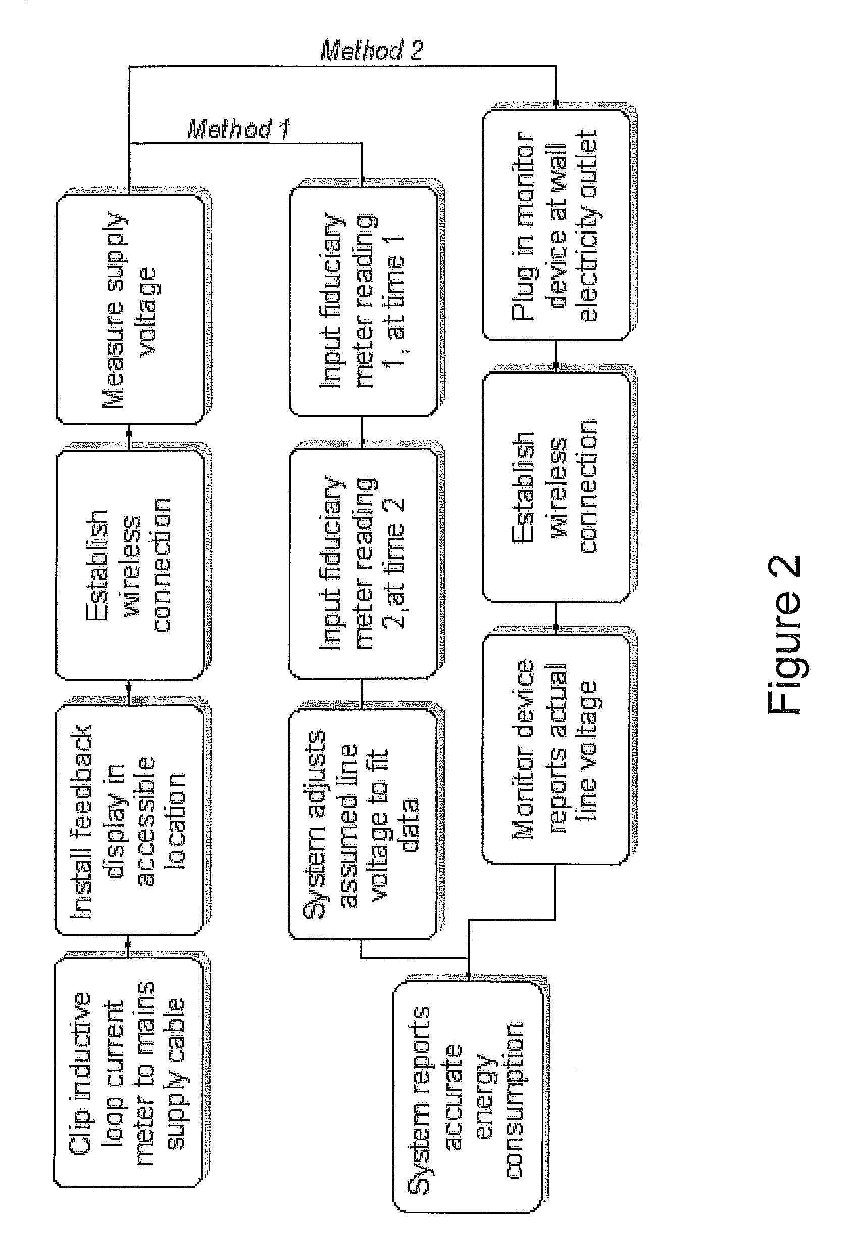
[0018]There is provided a combination of clip-on power monitors with automatic and user-friendly procedures and mechanisms for determining the local mains electrical supply voltage, in order to enhance accuracy and energy efficiency. In embodiments the monitor and / or display unit determines the voltage automatically from remote elements of the same system which are connected directly to the mains themselves or else obtain readings from the fiduciary meter for calibration purposes.
[0025]In some preferred embodiments of the system such a plug-through controller may be employed to measure the mains voltage. This is advantageous in part because such a device will generally already include a voltage sensor as well as a wireless communications link for connecting to a system controller. In embodiments either the system controller or the plug-through controller may be configured only to measure the mains voltage when any appliance connected to the plug-through controller is switched off (the plug-through controller may only measure at such times and / or the system controller may only use measurements made at such times). Whether the appliance is on or off can be determined by means of a current measuring device in the plug-through controller which, again, may be present for other reasons. By measuring when the appliance is off small voltage drops due to resistive losses in the local mains power distribution network may be avoided.
[0026]In other embodiments the voltage measurement system may comprise a user interface for the system controller to enable a user to input two readings of the electricity meter for the premises spaced apart by a time interval. This enables a one-off calibration of the system by adjusting and assumed voltage used by the system until the measured power consumption matches that over the same period deduced from the two meter readings. The user interface may be implemented, for example, as a website, optionally via a remote server where the system controller has a connection to the server over the internet With such an arrangement preferably the time interval is relatively long, for example a day, a week, or a fortnight as in this way it becomes less important for the user to precisely time when the electricity meter readings are made.
[0029]In some preferred implementations power consumption data from the system is uploaded to a central server and provided to a website to enable a user to compare their own power consumption with that of others, preferably those who are expected to have similar power consumption. The increased accuracy of power consumption determination provided by a system as described above is particularly helpful when making such comparisons between users.

Problems solved by technology

Because meters and their associated wiring are unsightly, they are usually sited in out-of-the-way and consequently hard to access locations.
Electricity suppliers typically employ corps of specialist staff to read customers' meters, at considerable expense.
Estimated readings can diverge significantly from real readings in the interval between meter readings, so customers are often invited to read and report their meter readings themselves—not always a straightforward task.
Automated Meter Reading (AMR) has the potential to greatly reduce the ongoing cost to suppliers of reading meters, but the capital outlay involved in deploying such technology has so far prevented its widespread use.
However, there is a problem in that its provision imposes extra costs on the supplier, who must provide some kind of display device to each customer, preferably separate and more accessible than the meter itself, in order to deliver energy usage feedback.
This is necessarily a costly operation.
In practice, for most domestic usage it is reasonable to assume unity power factor, although for some loads such as vacuum cleaner motors this assumption may result in some slight over-reporting of power consumption.
As discussed above, exact readings are not crucial to effective energy-use feedback, but errors of 10% do begin to undermine their usefulness.
In particular, it becomes difficult to compare data across locations, which is important if the objective is to tell users how they rank against similar users.
Users also trust the feedback less, making it less effective.

Method used


Image

  • Power consumption feedback systems
  • Power consumption feedback systems
  • Power consumption feedback systems

Examples


Embodiment Construction

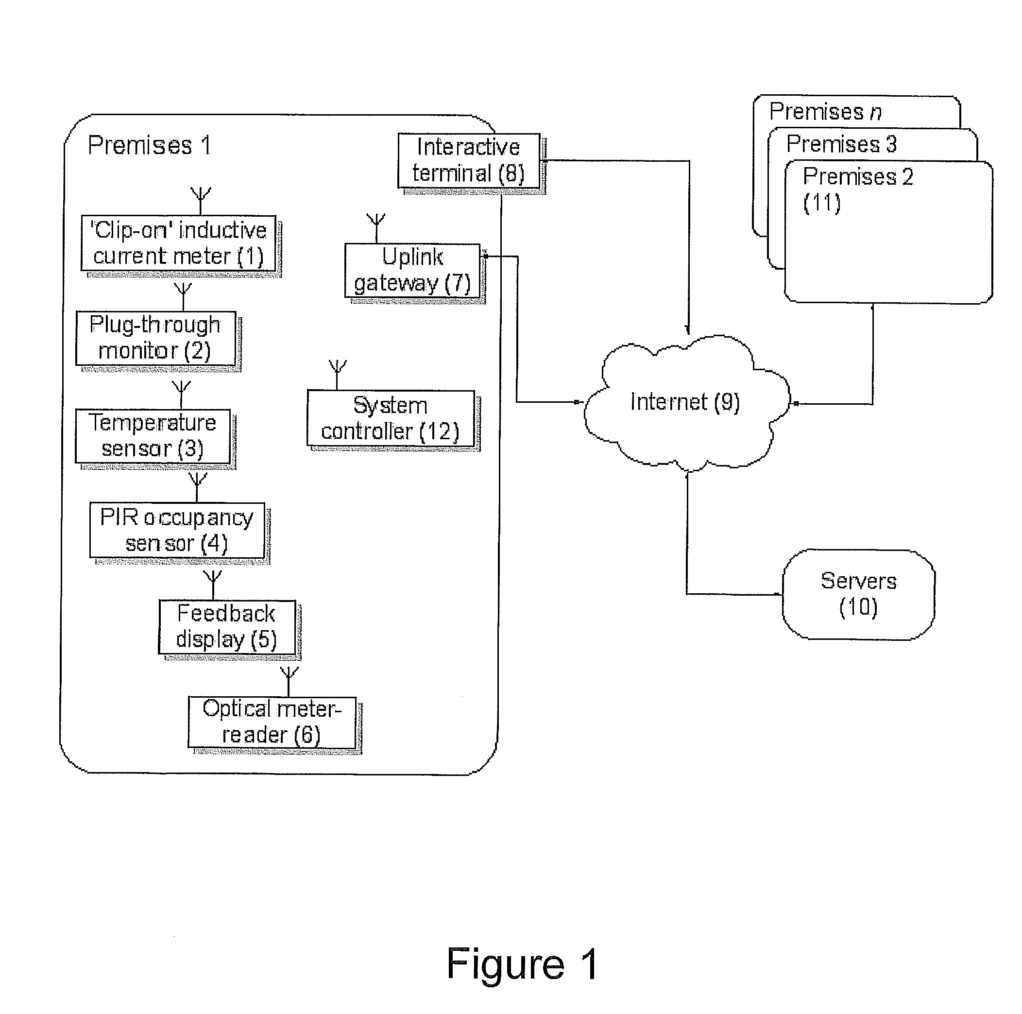
[0047]FIG. 1 shows schematically various components of a comparative energy feedback system. A customer's premises is outfitted with energy-related sensors including, of those shown, some subset. For accurate energy reporting the core elements are the “clip-on” inductive current meter (1), a system controller (12) and a feedback display (5).

[0048]The system controller (12) computer logic for calculating power usage from the current measurements may be separate, located remotely off site as part of a client-server application architecture, or co-located with the inductive current meter (1), the feedback display (5) or an uplink gateway (7). In any case at least two of these devices communicate using a local-area wireless communications protocol, using proprietary RF modulation schemes and protocols, or standards such as IEEE 802.15.4 (WiFi), Bluetooth®, or ZigBee®

[0049]Occupancy sensors (4) may be included in the system to allow the computer logic to change its behaviour according to...


PUM


Abstract

An electrical power supply consumption feedback system including a current transducer configured to be attached externally to a mains power supply cable providing a mains power supply to said building to measure a current of said mains power supply, a voltage measurement system configured to measure within said building a voltage of said mains power supply, a system controller coupled to said voltage measurement system and to said current transducer and having a system controller wireless interface, at least one of said current transducer and said voltage measurement system having a complementary wireless interface and being coupled to said system controller via the wireless interface, and wherein said system controller is configured to calculate a power consumption of said building from said measured current and voltage; and a display coupled to said system controller to display a visual indication of said calculated power consumption.

Description

RELATED APPLICATIONS[0001]This application claims the benefit of U.S. Provisional Application Ser. No. 61 / 075,056, filed Jun. 24, 2008, entitled POWER CONSUMPTION FEEDBACK SYSTEMS, the entire disclosure of which is herein incorporated by reference. This application claims foreign priority benefits of United Kingdom Application Ser. No. GB0810862.3, filed Jun. 13, 2008, entitled POWER CONSUMPTION FEEDBACK SYSTEMS, the entire disclosure of which is herein incorporated by reference.FIELD OF THE INVENTION[0002]This invention relates to apparatus, methods and computer program code for obtaining an accurate measurement of a premises' electrical energy consumption using an inductively-coupled electric current meter at the mains connection and one of several means of inferring the voltage remotely. Other aspects relate to encouraging energy efficiency by automatically providing feedback to users showing their energy consumption relative to that of other people.BACKGROUND OF THE INVENTION[00...

Claims


Application Information

Patent Timeline
Patent Type & Authority Applications(United States)
IPC IPC(8): G01R21/00G06F19/00
CPCG01R21/06G01R22/10G01R22/063G01R21/007G01R22/00
Inventor PHILLIPS, AMYAS EDWARD WYKES
Owner ALERTME COM
Learn More