
Method to tailor location of peak electric field directly underneath an extension spacer for enhanced programmability of a prompt-shift device

a technology of peak electric field and extension spacer, which is applied in the direction of semiconductor devices, electrical apparatus, transistors, etc., can solve the problems of increasing the overall production cost of the ic die, prompt-shift devices require extremely long (, 5 seconds) programming times, etc., and achieve the effect of enhancing the programmability of prompt-shift devices and reducing programming tim

Active Publication Date: 2009-12-03
GLOBALFOUNDRIES US INC
View PDF8 Cites 3 Cited by
  • Summary
  • Abstract
  • Description
  • Claims
  • Application Information

AI Technical Summary

Benefits of technology

[0010]The invention provides a method to enhance the programmability of a prompt-shift device, and thus reduce the programming time to sub-millisecond times.
[0012]As stated above, the invention provides a method to enhance the programmability of a prompt-shift device and thus reduce the programming time to sub-millisecond times, by altering the extension and halo implants (hereinafter halo / extension implants), instead of simply omitting the same from one side of the device as is the case in the prior art prompt-shift devices mentioned above.
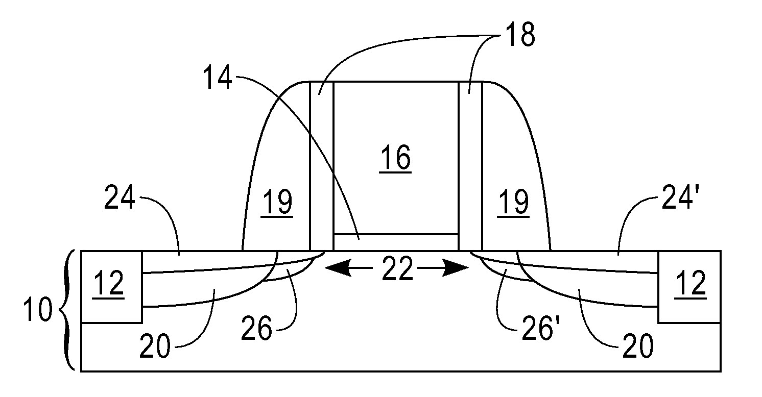
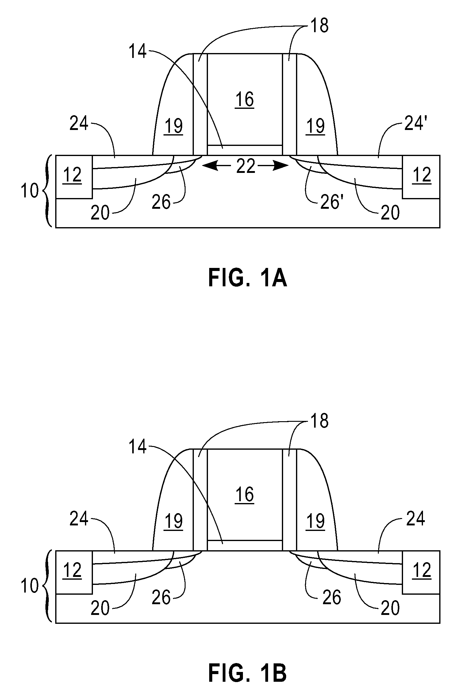
[0013]The invention uses an altered halo / extension implant to adjust (i.e., tailor) the junction profile to enhance the electric field directly beneath the extension dielectric spacer. One key feature of the altered implant in the invention is the halo (p-type for an nFET and n-type for a pFET) strength and location. In particular, the applicants have determined that increasing the halo dose (in a range from about 1.5 to 3 times greater the standard halo dose) enhances the electric field of the device during operation. Also, the applicants have determined that moving the halo implant after the extension dielectric spacer has been formed shifts the peak electric field to a location that is directly under the extension dielectric spacer. The term “peak electric field” denotes the region in the channel during the programming condition where the electric field is the highest. It is at this peak electric field location that electrons will have a maximum probability of being transferred from the channel into the above lying region. In comparison, and in conventional CMOS technology, it is common to perform the nFET extension and halo implants without the presence of any spacer. The pFET extension and halo implants in conventional CMOS processing are typically performed after the extension dielectric spacer has been formed.
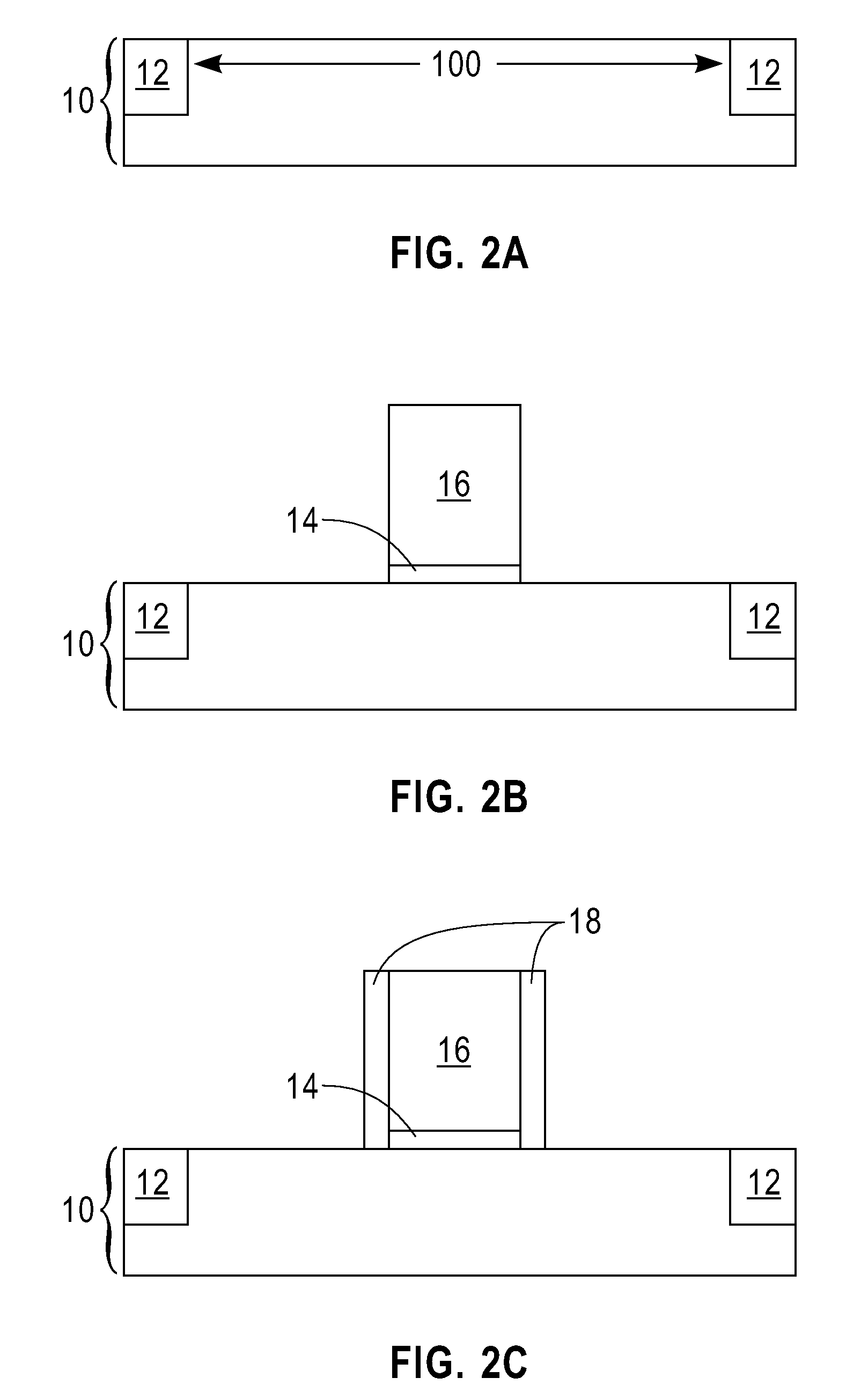
[0014]The present invention discloses two methods that can be used to fabricate a prompt-shift device in which the programmability thereof is less than 1 second, preferably within the sub-millisecond time range. In one embodiment of the present invention, no additional masks are used during the fabrication of the inventive prompt-shift device. In this embodiment of the invention, the altered halo / extension implant is performed to all the devices present on the substrate, e.g., the memory devices as well as the logic devices. Moreover, the no additional mask embodiment of the present invention provides a prompt-shift device including symmetric, yet altered halo / extension regions on both sides of the device. In another embodiment of the invention, an additional mask is used and is formed atop a portion of the memory device and the logic devices during the altered halo / extension implant. This embodiment of the invention permits the formation of asymmetric, yet altered halo / extension implant regions into only the memory devices independently from the other devices.

Problems solved by technology

The required programming voltage of prior art fuses and antifuses to implement OTP nonvolatile memory storage is quite high (on the order of 10-12 volts) and oftentimes the high-programming voltages must be routed to other circuits in the IC which are not typically capable of withstanding such high voltages.
In some instances, extra processing steps are needed which increase the overall production cost of the IC die.
In addition to requiring high-programming voltages, prior art fuses and antifuses occupy a large space on the IC die which detracts from the space were other ICs devices can be formed.
Although the prompt-shift device disclosed in the above references provides a means for programming a nonvolatile memory cell the prior art prompt-shift devices require extremely long (on the order of about 1 to about 5 seconds) programming times.

Method used


Image

  • Method to tailor location of peak electric field directly underneath an extension spacer for enhanced programmability of a prompt-shift device
  • Method to tailor location of peak electric field directly underneath an extension spacer for enhanced programmability of a prompt-shift device
  • Method to tailor location of peak electric field directly underneath an extension spacer for enhanced programmability of a prompt-shift device

Examples


Embodiment Construction

[0025]The present invention, which provides a prompt-shift device having enhanced programmability and a method of fabricating the same, will now be described in greater detail by referring to the following discussion and drawings that accompany the present application. It is noted that the drawings of the present application are provided for illustrative purposes only, and as such, the drawings are not drawn to scale.

[0026]In the following description, numerous specific details are set forth, such as particular structures, components, materials, dimensions, processing steps and techniques, in order to provide a thorough understanding of the present invention. However, it will be appreciated by one of ordinary skill in the art that the invention may be practiced without these specific details. In other instances, well-known structures or processing steps have not been described in detail in order to avoid obscuring the invention.

[0027]It will be understood that when an element as a l...


PUM


Abstract

The invention provides a method to enhance the programmability of a prompt-shift device, which reduces the programming time to sub-millisecond times, by altering the extension and halo implants, instead of simply omitting the same from one side of the device as is the case in the prior art prompt-shift devices. The invention includes an embodiment in which no additional masks are employed, or one additional mask is employed. The altered extension implant is performed at a reduced ion dose as compared to a conventional extension implant process, while the altered halo implant is performed at a higher ion dose than a conventional halo implant. The altered halo / extension implant shifts the peak of the electrical field to under an extension dielectric spacer.

Description

FIELD OF THE INVENTION[0001]The present invention relates to a nonvolatile memory cell. More particularly, the present invention relates to a nonvolatile memory cell including at least one field effect transistor (FET) that has enhanced programmability. The invention also provides a method of fabricating such a nonvolatile memory cell.BACKGROUND OF THE INVENTION[0002]In the semiconductor industry, it is oftentimes desirable to fabricate a very large-scale integrated (VLSI) circuit which includes a one-time programmable (OTP) nonvolatile memory element that can be programmed either during wafer probing or after packaging of the semiconductor die. For example, programming of an OTP nonvolatile memory element is used to provide self-contained identification information about an individual IC die or die revision. OTP nonvolatile memory can also be used for remapping addresses of defective DRAM (dynamic random access memory) cells so that functional redundant memory cells are addressed i...

Claims


Application Information

Patent Timeline
Patent Type & Authority Applications(United States)
IPC IPC(8): H01L29/78H01L21/336
CPCH01L21/26513H01L21/26586H01L21/266H01L29/1083H01L29/66477H01L29/66833H01L29/7834H01L29/792H01L29/6659H01L21/26546
Inventor BREITWISCH, MATTHEW J.CHEEK, ROGER W.JOHNSON, JEFFREY B.LAM, CHUNG H.RAINEY, BETH A.ZIERAK, MICHAEL J.
Owner GLOBALFOUNDRIES US INC
Learn More