
Continuous mass production of carbon nanotubes in a nano-agglomerate fluidized-bed and the reactor

a technology of carbon nanotubes and fluidized beds, applied in the direction of physical/chemical process catalysts, metal/metal-oxide/metal-hydroxide catalysts, chemistry apparatuses and processes, etc., can solve the problems of high production cost, mass production of carbon nanotubes, and commercial application that has not been realized, and achieve excellent adaptability of the reactor system

Inactive Publication Date: 2009-11-19
TSINGHUA UNIV
View PDF9 Cites 58 Cited by
  • Summary
  • Abstract
  • Description
  • Claims
  • Application Information

AI Technical Summary

Benefits of technology

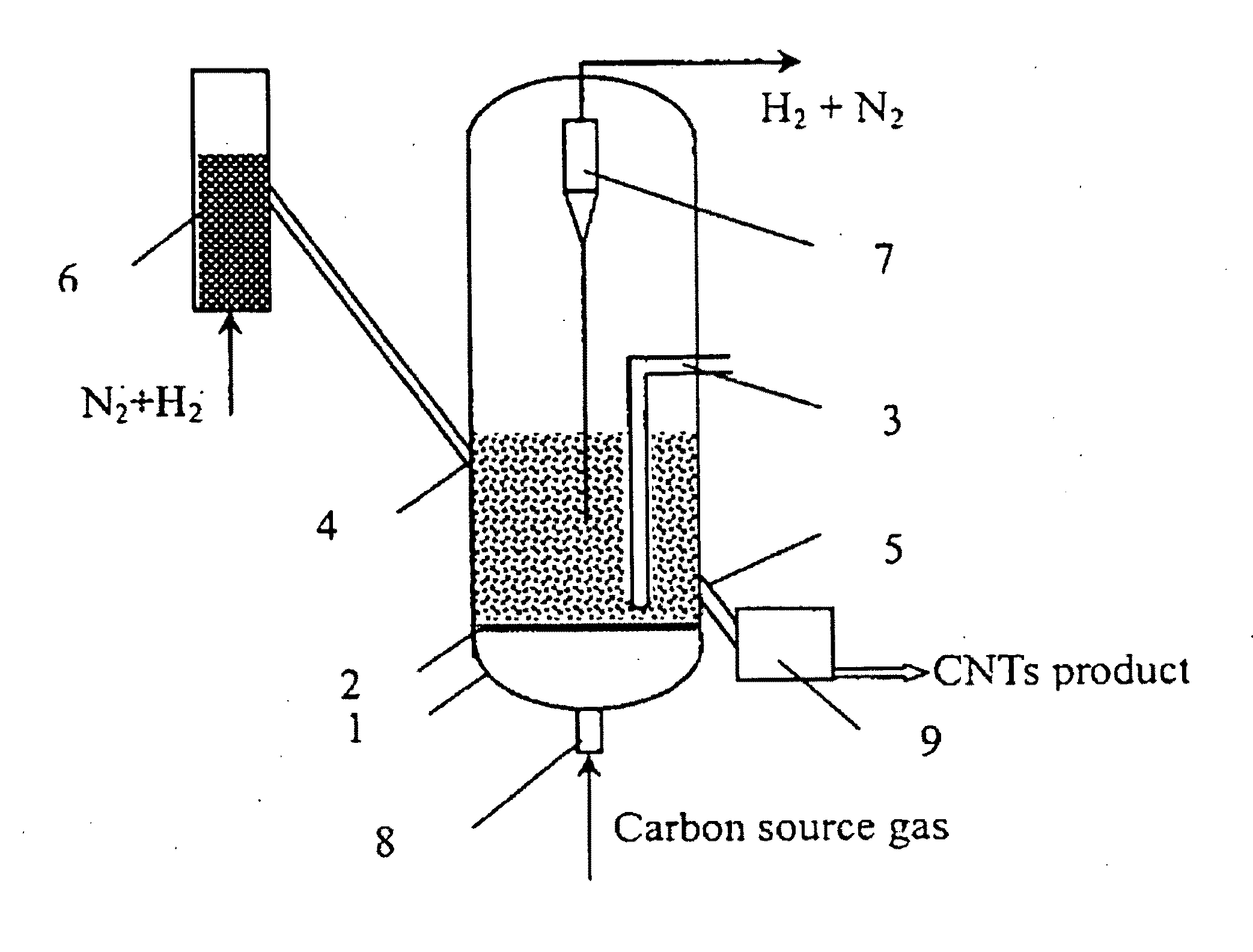
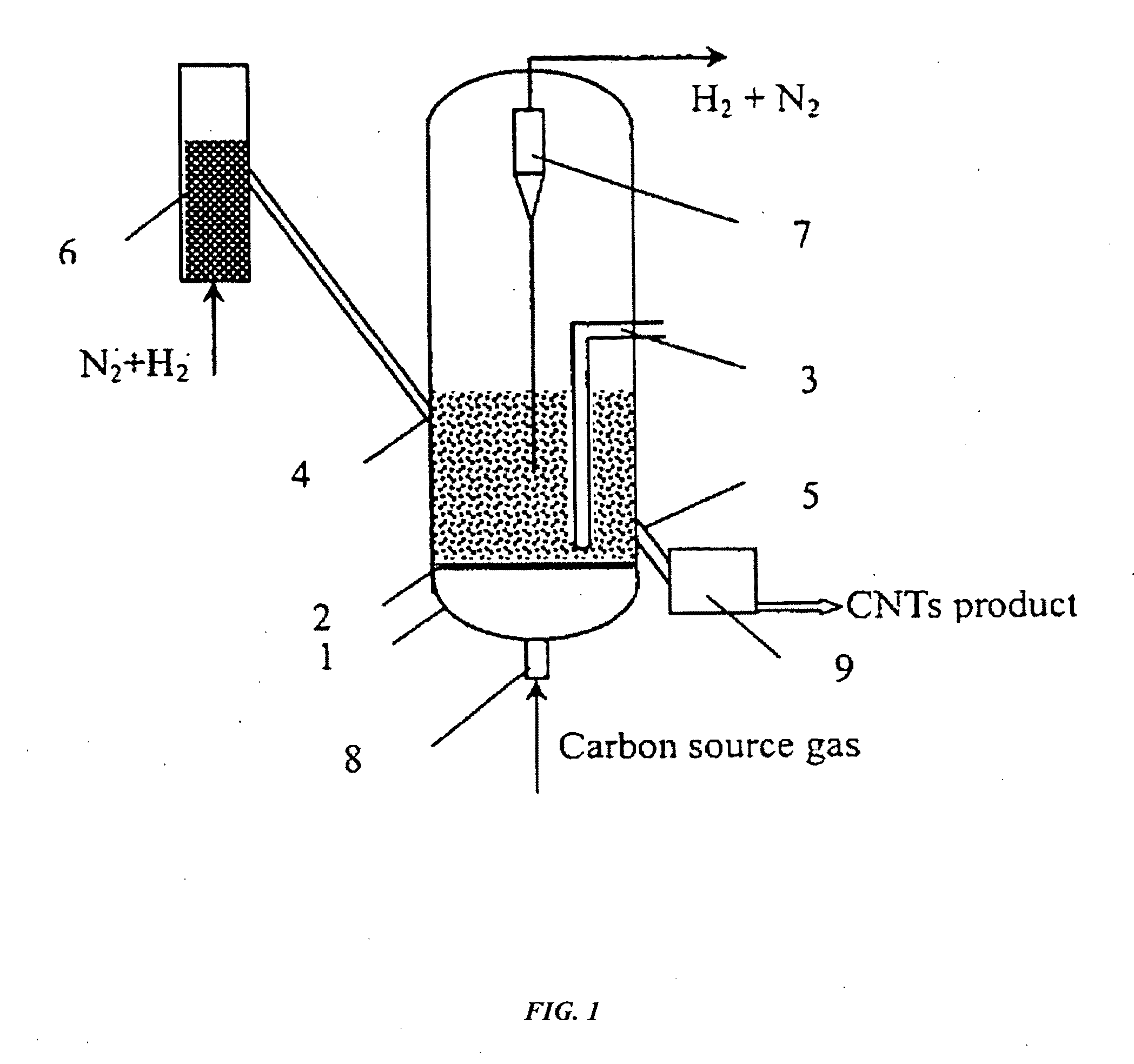
[0006]The object of the present invention is to provide a method and reaction apparatus for continuous production of carbon nanotubes in a nano-agglomerate fluidized bed, wherein the agglomeration and aggregation behaviors of nano-particles are taken into consideration. Normal fluidization state or even particulate fluidization state can be realized and maintained during the whole reaction process through proper control of the structure and growth of carbon nanotubes based on the analysis of the growth, agglomeration and fluidization of carbon nanotubes during the chemical vapor deposition process. By properly adjusting the reaction rate, operating conditions and fluidized-bed structure, the reactor bed is kept in an agglomerate fluidization state, so as to realize the continuous mass production of carbon nanotubes with a high degree of crystallization, high purity, and high yield. In certain instances, the carbon nanotubes produced have a purity of greater than 96% and a yield of greater than >26 g / per gram of catalyst.
[0020]The catalyst support can be selected from powders with good flowability, such as superfine glass beads, silicon dioxide, alumina and carbon nanotubes. By adopting the process, conditions and reactors of the present invention, carbon nanotubes having a loose agglomerated structure can be produced with agglomerate diameters of 1˜1000 μm, bulk density of 20˜800 kg / m3, and with good flowability / fluidization properties.
[0022]1. It makes good use of the specific characteristics of the fluidized bed, and it has compact structure and good applicability.
[0023]2. The stuffs in the reactor are of an appropriate density such that they can be kept in a state of flow / fluidization, and this provides sufficient growing space for the carbon nanotubes and also obtains sufficient reaction capacity.
[0024]3. It can continuously supply the catalyst into and remove the carbon nanotube product out of the reactor, thus a continuous mass production can be achieved.
[0026]5. It can supply heat in and remove heat out of a scaled-up apparatus, and is suitable for the exothermic or endothermic catalytic decomposition processes. 6. The adaptability of the reactor system is excellent. The locations of the feed inlet and product outlet can be adjusted according to the requirements of the reaction residence time and the structure of the products.

Problems solved by technology

The exceptional mechanical and electrical properties of carbon nanotube have attracted intensive attention of physicists, chemists and material scientists worldwide, however, its commercial application has not been realized yet.
The reasons lie in two interrelated aspects: the difficulty in mass production of carbon nanotubes and hence the high production cost.
Thus, in order to take carbon nanotubes from laboratory to market, mass production of high-quality carbon nanotubes is one of the principal challenges to take.
However, traditional gas-solid fluidized beds are only used for the fluidization of non-C-type powders with diameters larger than 30 μm (Geldart D. Powder Technology, 1973, 7: 285).
The growth of one dimensional materials and their adherence to each other in the preparation of carbon nanotubes by chemical vapor deposition tend to make fluidization difficult, and thus cause coagulation, uneven distribution of temperature and concentrations, and the deposition of carbon among particles.
Therefore, there has been no report on the application of fluidized-bed reactor in continuous mass production of carbon nano-materials.

Method used


Image

  • Continuous mass production of carbon nanotubes in a nano-agglomerate fluidized-bed and the reactor
  • Continuous mass production of carbon nanotubes in a nano-agglomerate fluidized-bed and the reactor
  • Continuous mass production of carbon nanotubes in a nano-agglomerate fluidized-bed and the reactor

Examples


example 1

[0036]1. Loading Fe—Cu transition metal oxides on a SiO2 support.

[0037]2. Adding the above supported catalyst into the catalyst activation reactor and carrying out the reduction reaction by flowing a mixture of hydrogen and nitrogen into the reactor at 650° C., wherein the volume ratio of hydrogen to nitrogen was 1:0.5 and the space velocity of the reduction reaction was 0.5 h−1.

[0038]3. Transporting the reduced catalyst into the fluidized bed with temperature at 700° C., feeding a mixture of hydrogen, ethylene and nitrogen into the reactor, wherein the volume ratio of H2:C2H4:N2 was 1:1:1 and the space velocity during the reaction was kept at 10000 h−1 and the superficial gas velocity was 0.5 m / s.

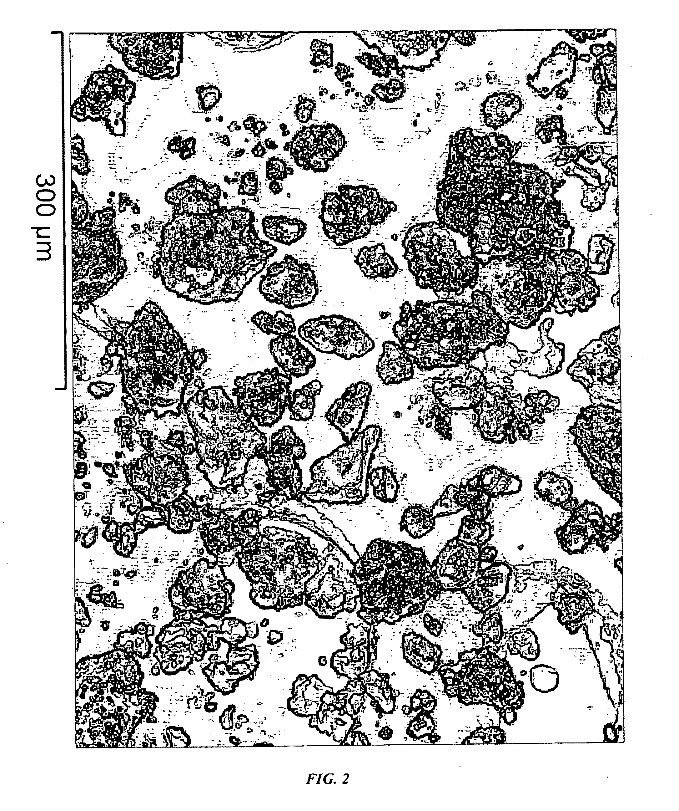
[0039]FIG. 2 shows a typical SEM photo of the carbon nanotubes produced in the example 1. The sample was directly obtained from the reactor and was not subjected to any purification nor pulverization. The carbon nanotubes are in the form of agglomerates, and most of the agglomerates are ne...

example 2

[0042]1. Loading Ni—Cu transition metal oxides on a glass bead support.

[0043]2. Adding the above supported catalyst into the catalyst activation reactor and carrying out the reduction reaction by flowing a mixture of hydrogen and nitrogen into the reactor at 520° C., wherein the volume ratio of hydrogen to nitrogen was 1:1 and the space velocity of the reduction reaction was 2 h−1.

[0044]3. Transporting the reduced catalyst into the fluidized bed with temperature at 520° C., feeding a mixture of hydrogen, propylene and nitrogen into the reactor, wherein the volume ratio of H2:C3H6:N2 is 1:1:1 and the space velocity during the reaction was kept at 5 h−1 and the superficial gas velocity was 0.09 m / s.

example 3

[0045]1. Loading Co—Mn transition metal oxides on a Al2O3 support.

[0046]2. Adding the above supported catalyst into the catalyst activation reactor and carrying out the reduction reaction by flowing a mixture of hydrogen and nitrogen into the reactor at 800° C., wherein the volume ratio of hydrogen to nitrogen was 1:0.5 and the space velocity of the reduction reaction was 0.3 h−1.

[0047]3. Transporting the reduced catalyst into the fluidized bed with temperature at 870° C., feeding a mixture of hydrogen, methane and nitrogen into the reactor, wherein the volume ratio of H2:CH4:N2 was 0.5:1:0.1 and the space velocity during the reaction was kept at 5000 h−1, and the superficial gas velocity was 0.8 m / s.


PUM

PropertyMeasurementUnit
Lengthaaaaaaaaaa
Lengthaaaaaaaaaa
Lengthaaaaaaaaaa

Abstract

The present invention relates to a method for continuous production of carbon nanotubes in a nano-agglomerate fluidized bed, which comprises the following steps: loading transition metal compounds on a support, obtaining supported nanosized metal catalysts by reducing or dissociating, catalytically decomposing a carbon-source gas, and growing carbon nanotubes on the catalyst support by chemical vapor deposition of carbon atoms. The carbon nanotubes are 4˜100 nm in diameter and 0.5˜1000 μm in length. The carbon nanotube agglomerates, ranged between 1˜1000 μm, are smoothly fluidized under 0.005 to 2 m / s superficial gas velocity and 20-800 kg / m3 bed density in the fluidized-bed reactor. The apparatus is simple and easy to operate, has a high reaction rate, and it can be used to produce carbon nanotubes with high degree of crystallization, high purity, and high yield.

Description

CROSS-REFERENCES TO RELATED APPLICATIONS[0001]This application is a continuation-in-part of U.S. application Ser. No. 10 / 478,512 filed Nov. 24, 2003, which is a National Stage Entry of PCT / CN02 / 00044 filed Jan. 29, 2002 which claims benefit of priority to Chinese Patent Application No. CN 01118349.7 filed May 25, 2001.BACKGROUND OF THE INVENTION[0002]It is more than a decade since the first report on carbon nanotube as a new material. The exceptional mechanical and electrical properties of carbon nanotube have attracted intensive attention of physicists, chemists and material scientists worldwide, however, its commercial application has not been realized yet. The reasons lie in two interrelated aspects: the difficulty in mass production of carbon nanotubes and hence the high production cost. For instance, the international market price of carbon nanotubes of 90% purity is as high as $60 / g, which is 5 times that of gold. It is reported that the highest production rate of carbon nanot...

Claims


Application Information

Patent Timeline
IPC IPC(8): B01J21/18B82B1/00
CPCB01J8/0055C01B2202/36B01J21/04B01J21/08B01J21/185B01J23/70B01J23/745B01J23/75B01J23/755B01J23/8892B01J2208/00132B01J2219/00033B82Y30/00B82Y40/00C01B31/0233C01B31/024C01B2202/06C01B2202/34B01J8/1836C01B32/162C01B32/164
Inventor WEI, FEIWANG, YAOLUO, GUOHUAYU, HAOLI, ZHIFEIQIAN, WEIZHONGWANG, ZHANWENJIN, YONG
Owner TSINGHUA UNIV
Learn More