Eureka AIR delivers breakthrough ideas for toughest innovation challenges, trusted by R&D personnel around the world.

Application device for a breathing mask arrangement

a breathing mask and application device technology, applied in breathing masks, breathing protection, respirators, etc., can solve the problems of serious adverse effects on the comfort of wearing the breathing mask arrangement, and achieve the effect of more comfort for patients and reliable holding in the application position

Active Publication Date: 2006-06-13
RESMED HUMIDIFICATION TECH
View PDF7 Cites 103 Cited by
  • Summary
  • Abstract
  • Description
  • Claims
  • Application Information

AI Technical Summary

Benefits of technology

[0003]One aspect of the present invention is to provide an application device for a breathing mask arrangement, by which a breathing mask arrangement can be reliably held in the application position and which provides more comfort to the patient.
[0005]The application device allows the breathing mask arrangement to be supported in the forehead region of the mask user by way of a forehead support device which can advantageously be adapted to different facial architectures.
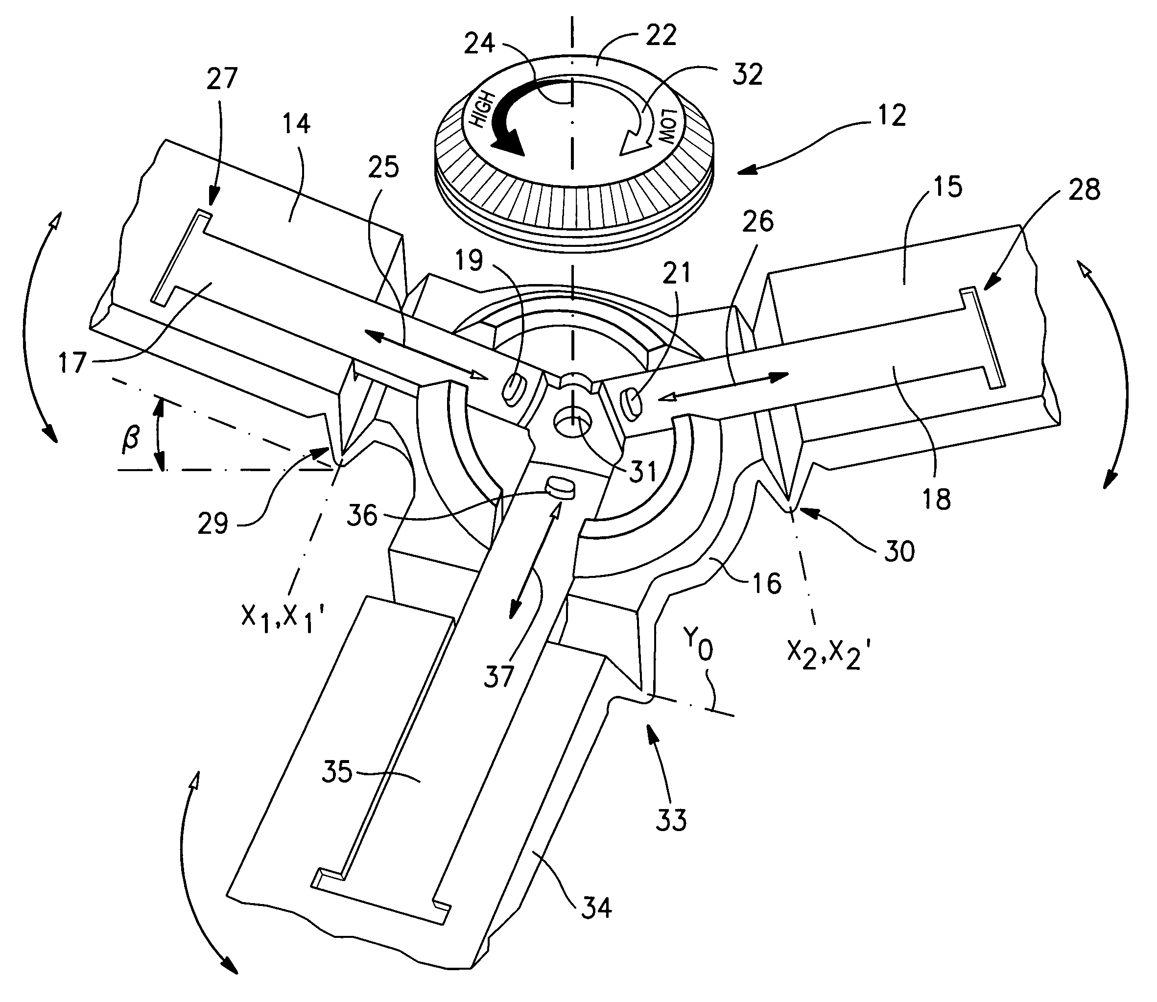
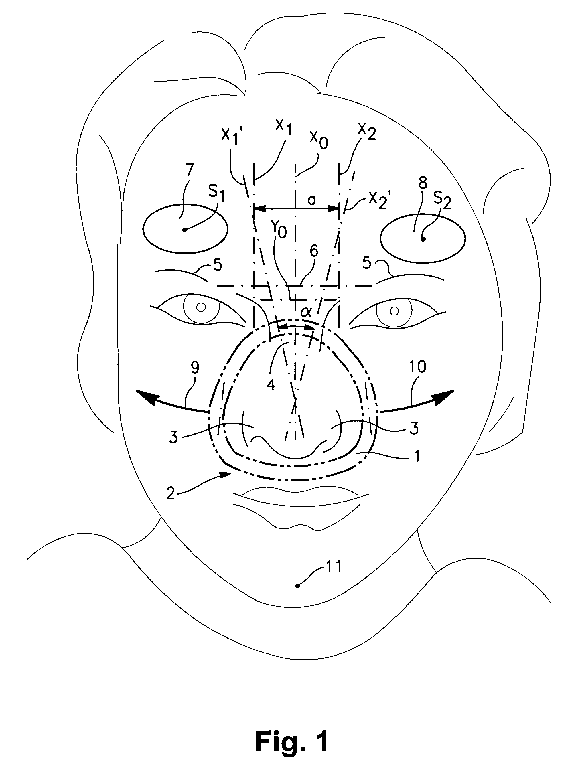
[0007]According to one embodiment, the pivot axes of each of arm elements are directed such that viewed in the application position in a front view, they extend transversely, e.g., substantially perpendicular, with respect to a transverse line joining the eyebrows. That advantageously makes it possible for the forehead support device to be precisely adapted to the curvature of the forehead of the user of the mask and thereby to precisely set the breathing mask which is held by the application device in the region of the contact zone of the sealing lip device, which contact zone crosses over the bridge of the nose.
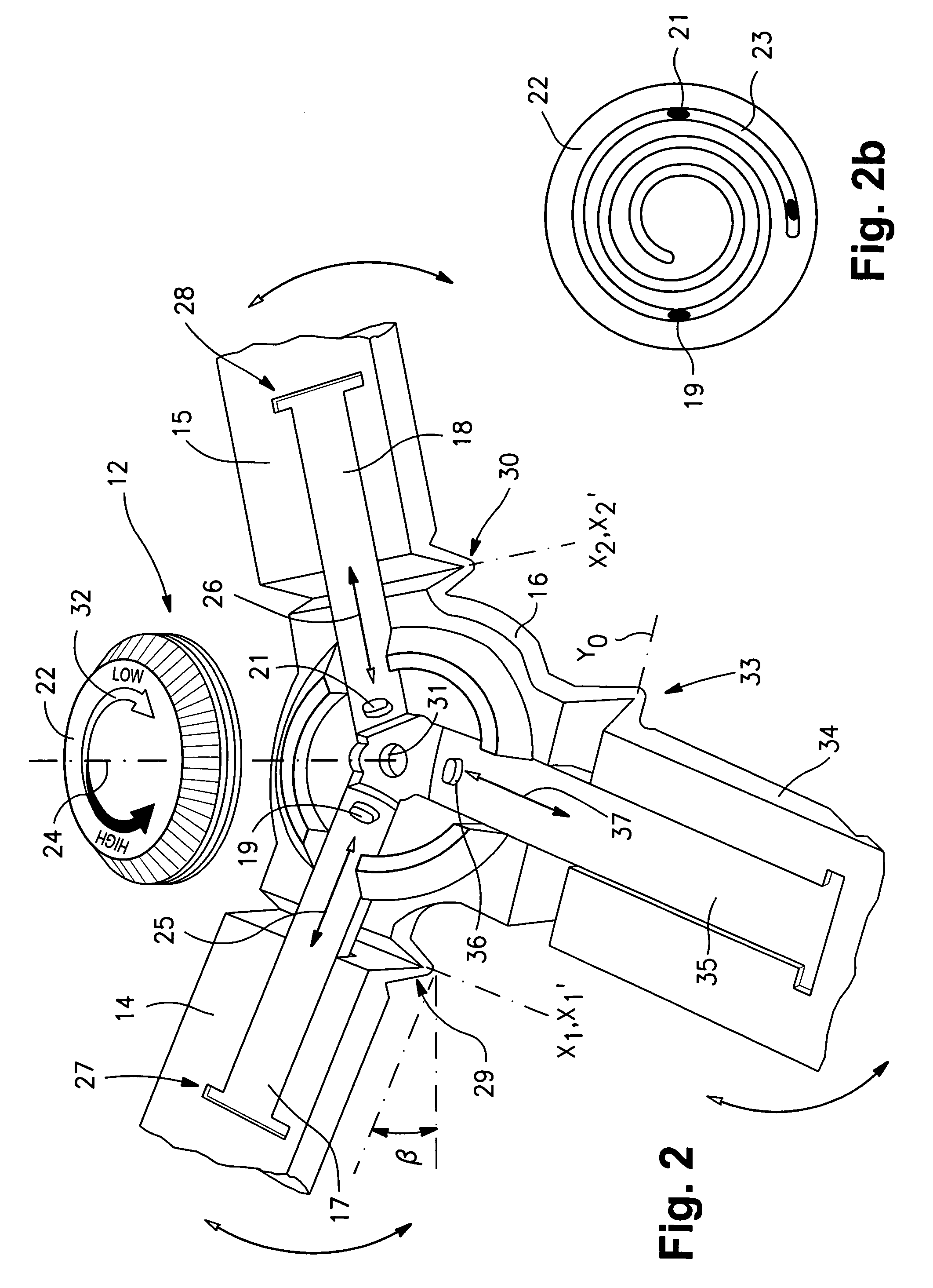
[0009]According to another aspect of the present invention, adaptability of the forehead support device to the individual curvature of the forehead of the user of the mask can be further increased if the pivot axes of the arm members are inclined relative to each other through an angle α in the range of 8 and 45° relative to each other. In one embodiment, the structure defining the pivot axes can be designed in such a way that the angle α of the pivot axes relative to each other is adjustably variable.
[0010]In one embodiment, the pivot axes are established in such a way that, in relation to a front view of a user of the mask, they intersect in the region between the transverse line joining the eyebrows and the chin of the user of the mask. That affords particularly good compatibility in relation to the facial architectures which statistically predominantly prevail.
[0012]In accordance with another aspect of the present invention, the adjusting drive device according to one embodiment includes an adjusting wheel which is coupled by way of a spiral structure to actuating members. Thus, the arm elements can be deflected into defined pivotal positions. In one embodiment, the adjusting wheel is mounted rotatably about an axis which in the application position of the application device is oriented substantially perpendicularly to the surface of the forehead of the patient. The adjusting wheel of one embodiment has a diameter in the range of 20 and 50 mm and in the outside peripheral region it is provided with a profiling, e.g., a fluted or grooved structure, which permits the reliable transmission of the finger forces for rotating the adjusting wheel. The adjusting wheel according to one embodiment is arranged in an intermediate region between a respiratory gas conduit portion of the breathing mask arrangement and a base portion of the forehead support device. In that case it is possible for the finger forces for rotating the adjusting wheel to be applied by way of the thumb and the index finger, for example, in which case the respiratory gas conduit associated with the breathing mask arrangement is embraced by the fingers, by using the thumb and the index finger.

Problems solved by technology

Under some circumstances, in the region in which the sealing lip device is applied and in the contact region of the forehead support device, surface pressures can occur, which result in the level of comfort involved in wearing the breathing mask arrangement being seriously adversely affected.

Method used


Image

  • Application device for a breathing mask arrangement
  • Application device for a breathing mask arrangement
  • Application device for a breathing mask arrangement

Examples


Embodiment Construction

[0028]FIG. 1 shows a front view illustrating the surface of the face of a user of a breathing mask arrangement. For application or fitting of a breathing mask arrangement it is applied for example to the face of the mask user in such a way that a sealing lip contact zone 1 defined by a sealing lip device of the breathing mask arrangement and the surface of the face of the mask user, starting from the upper lip region 2, extends around the nostrils 3 to the bridge of the nose 4 and, e.g., passes across same at the level of the eyes.

[0029]The breathing mask arrangement according to one embodiment is supported on the forehead region of the mask user by way of a forehead support device which will be described in greater detail hereinafter. As shown in FIG. 1, support on the forehead region is implemented by way of two contact zones 7, 8 which are disposed above a transverse line 6 which joins the eyebrows 5. In the view illustrated, support for the breathing mask arrangement in the fore...


PUM


Abstract

An application device for a breathing mask arrangement includes a base portion, a holding portion structured to support a mask and pivotally mounted to the base portion for pivotal movement about a first pivot axis, a right arm element pivotally mounted to the base portion for pivotal movement about a second pivot axis, and a left arm element pivotally mounted to the base portion for pivotal movement about a third pivot axis. The right and left arm elements are each provided with a contact portion for bearing against a right and a left forehead zone respectively of a mask user. The holding portion, the right arm element, and left arm element can be pivoted with respect to the base portion about the respective first, second, and third pivot axes.

Description

FIELD OF THE INVENTION[0001]The invention relates to an application device for a breathing mask arrangement as can be used, for example, in the context of CPAP-therapy for treating sleep-related respiratory disturbances.BACKGROUND OF THE INVENTION[0002]In the context of what is referred to as CPAP-therapy, a patient can be supplied by way of a breathing mask arrangement with a breathable gas, in particular ambient air, at a pressure level which is above the ambient pressure. The increased pressure which is applied by the respiratory gas makes it possible to provide for pneumatic splinting of the respiratory tracts and thus to obviate any obstructions. In that connection the breathing mask arrangement is worn by the patient over the entire sleep or rest phase of the patient. The breathing mask arrangement is usually supported by way of a sealing lip zone in the region around the nose of the person using the mask and by way of a forehead support device in the forehead region of the ma...

Claims


Application Information

Patent Timeline
IPC IPC(8): A62B18/08A61M16/06
CPCA61M16/06A61M16/0644A61M16/0633A61M16/0683A61M16/0611A61M16/0638A61M16/0655
Inventor HEIDMANN, DIETERBRANDMEIER, RICHARDMADAUS, STEFANVOEGELE, HARALD
Owner RESMED HUMIDIFICATION TECH
Why Eureka
Eureka Blog
Learn More