
Multi-wavelength diagnostic imager

a multi-wavelength, diagnostic imaging technology, applied in the direction of instruments, patient positioning for diagnostics, application, etc., can solve the problems of lack of physiological data from patients directly relating to tissue degradation, lack of sufficient standardized care protocols, and inability to meet patient needs, etc., to reduce or eliminate specular and near-surface reflectance

Inactive Publication Date: 2009-11-05
BOARD OF RGT THE UNIV OF TEXAS SYST
View PDF13 Cites 52 Cited by
  • Summary
  • Abstract
  • Description
  • Claims
  • Application Information

AI Technical Summary

Benefits of technology

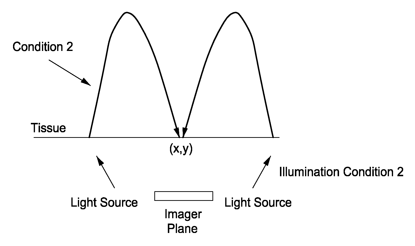
[0007]The present invention is an imaging apparatus and method for multi-wavelength detection and imaging. The present invention includes an apparatus and method for noninvasive evaluation of a target versus a non-target, comprising: one or more light sources having at least one emission spectra directed at the target wherein the position, orientation and intensity of light sources is varied to control near-surface reflectance and are directed at less than the entire target; and one or more detectors positioned to capture light reflected from the target into two or more spatial images of the target at two or more times, wherein the spatial images are used to distinguish between the target and the non-target. In one aspect, the apparatus further comprising a processor in communication with the one or more detectors, wherein the processor further calculates a transform of the time variations of at least a portion of the spatial images to distinguish between target and non-target image information to measure the presence of one or more factors that lead to changes in tissue health selected from decubitus ulcers, cancerous lesions, skin transfers, skin temperature, skin oxygenation, burns, skin trauma, skin diseases, autoinflammatory diseases, autoimmune diseases, infectious diseases, and combinations thereof. In one aspect, the position, orientation and intensity of light sources is selected to reduce or eliminate specular and near-surface reflectance.
[0010]In one aspect of the apparatus of the present invention the transform of the time variations of at least a portion of the spatial image information is a discrete Fourier transform. In another aspect, the processor of the apparatus of the present invention further calculates a transform of at least a portion of the spatial image information to further distinguish between target and non-target image information based on differing inverse spatial behaviors. In yet another aspect the position, orientation and intensity of light sources in the apparatus of the present invention is selected to reduce or eliminate specular reflectance.
[0020]In one aspect of the detection method of the present invention the transform of the time variations of at least a portion of the spatial image information is a discrete Fourier transform. In another aspect of the detection method of the present invention, wherein the processor further calculates a transform of at least a portion of the spatial image information to further distinguish between target and non-target image information based on differing inverse spatial behaviors. In yet another aspect of the detection method the position, orientation and intensity of light sources are selected to reduce or eliminate specular reflectance. In a further aspect of the detection method of the present invention, the target is suspected of having a decubitus ulcer or precursor thereof.
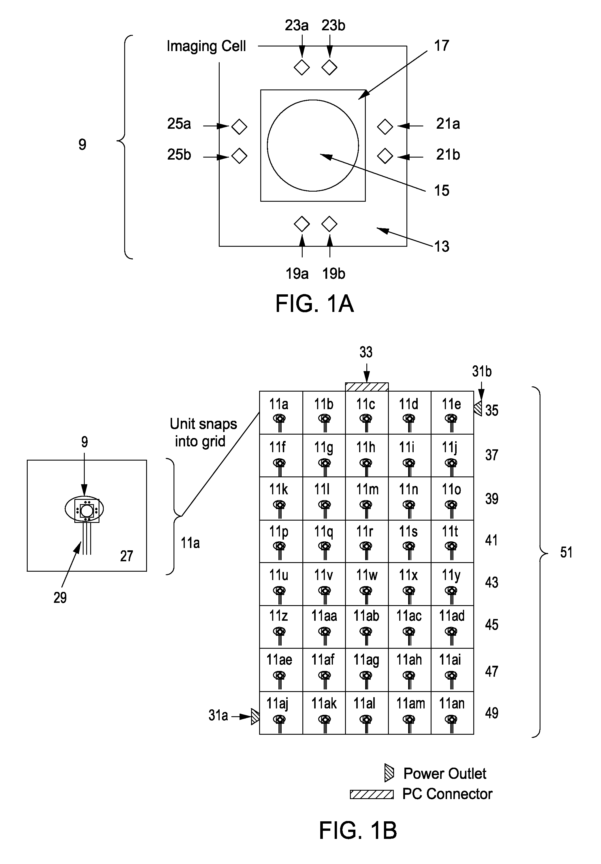
[0028]In a further embodiment the apparatus of the present invention is utilized for noninvasive measurement of physiological conditions on the surface of the skin, and comprises: (i) a base comprising two or more arrays, each array comprising two or more light sources with each of the light sources having a defined emission spectra and angle of illumination, and one or more detectors positioned to receive light from the skin, wherein the light source emission angles are selected to optimize the amount of light that is transmitted through an interface between the light array and the skin, while minimizing the light that is reflected off of the surface that would be directly incident on the detector; (ii) a processor in communication with the light sources and one or more detectors, wherein the processor calculates a transform of the time variations of the at least a portion of the spatial images to distinguish between target and non-target image information based on differing frequency behaviors; and (iii) an input / output modules connected to the processor that provides optical and / or electrical signals between the base module and a source of electrical power for the processor, the light sources and the detectors.

Problems solved by technology

Currently, no sufficient standardized care protocol has been accepted for ulcer prevention, and nurses are largely left with the physical burden of moving the patient every two hours while visually observing the skin for signs of obvious breakdown.
However, the problem with every existing approach lies in the lack of any physiological data from the patient that directly relates to tissue degradation.
While the presence of pressure is necessary for bed sore formation, it is not a sufficient condition.
By the time that visual degeneration is noticed, substantial tissue death below the skin surface has already occurred.
This delayed detection results in decubitus ulcers that, once treated, may take two years to return to original tissue health.
As a high-cost and high-volume problem in hospitals today, care protocols must move away from efficient treatment towards automated and effective prevention of decubitus ulcers.

Method used


Image

  • Multi-wavelength diagnostic imager
  • Multi-wavelength diagnostic imager
  • Multi-wavelength diagnostic imager

Examples


Embodiment Construction

[0084]While the making and using of various embodiments of the present invention are discussed in detail below, it should be appreciated that the present invention provides many applicable inventive concepts that can be embodied in a wide variety of specific contexts. The specific embodiments discussed herein are merely illustrative of specific ways to make and use the invention and do not delimit the scope of the invention.

[0085]To facilitate the understanding of this invention, a number of terms are defined below. Terms defined herein have meanings as commonly understood by a person of ordinary skill in the areas relevant to the present invention. Terms such as “a”, “an” and “the” are not intended to refer to only a singular entity, but include the general class of which a specific example may be used for illustration. The terminology herein is used to describe specific embodiments of the invention, but their usage does not delimit the invention, except as outlined in the claims.

[...


PUM


Abstract

The present invention is a multi-wavelength diagnostic imager. In one embodiment, the present invention includes an apparatus and method for noninvasive evaluation of a target versus a non-target, comprising: one or more light sources having at least one emission spectra directed at the target wherein the position, orientation and intensity of light sources is varied to control near-surface reflectance and are directed at less than the entire target; and one or more detectors positioned to capture light reflected from the target into two or more spatial images of the target at two or more times, wherein the spatial images are used to distinguish between the target and the non-target.

Description

CROSS-REFERENCE TO RELATED APPLICATIONS[0001]This application claims priority to U.S. Provisional Application Ser. No. 61 / 146,223, filed Jan. 21, 2009 and U.S. Provisional Application Ser. No. 61 / 049,243, filed Apr. 30, 2008.TECHNICAL FIELD OF THE INVENTION[0002]The present invention relates in general to the field of noninvasive medical imaging, and more particularly, to the design and application of multi-wavelength imaging to distinguishing between a target and a non-target based on the differing frequency behaviors of the spatial images, for example, patient care.STATEMENT OF FEDERALLY FUNDED RESEARCH[0003]None.BACKGROUND OF THE INVENTION[0004]Without limiting the scope of the invention, its background is described in connection with devices that aid in patient diagnosis, care and treatment.[0005]Modern day decubitus ulcer prevention involves inexact nursing protocols and a variety of questionable products lacking clinically verifiable patient outcomes. This situation is today's...

Claims


Application Information

Patent Timeline
IPC IPC(8): A61B6/00
CPCA61B5/00A61B5/6887A61B6/04A61B6/56A61G2210/20A61G7/1025A61B5/0059A61B5/447A61B2576/00A61G7/015G01N21/8851A61B5/0077A61B5/445G16H40/63
Inventor MELENDEZ, JOSEWATSON, JAMESDIMAIO, JOHN MICHAELMOZA, ROMA
Owner BOARD OF RGT THE UNIV OF TEXAS SYST
Learn More