Venturi Nozzle Aerodynamic Vent Design

Inactive Publication Date: 2009-11-05
RASSINI FRENOS S A DE
View PDF14 Cites 6 Cited by
  • Summary
  • Abstract
  • Description
  • Claims
  • Application Information

AI Technical Summary

Benefits of technology

[0010]In a highly advantageous embodiment of the invention, the first and second rotor plates have an annular central region therebetween that has a reduced axial distance to create an annular venturi effect in a substantially radial airflow.
[0012]In a highly advantageous embodiment of the invention, the airfoil-shaped structure is configured as an airfoil-shaped pillar. A plurality of airfoil-shaped pillars arranged in an annular row of airfoil-shaped pillars, and advantageously in a plurality of such rows. As such, the vent configuration forms a corresponding plurality of effective venturi nozzles. In accordance with a further aspect of the invention, there is further provided a plurality of airfoil-shaped fins arranged intermediate of the plurality of rows of airfoil-shaped pillars. In certain embodiments, the airfoil-shaped fins cooperate with the rotor plates to produce a plurality of effective venturi nozzles that enhance the rate of airflow between the rotor plates and the consequent removal of heat therefrom. However, a further venturi effect is obtained along the annulus of the rotor to enhance the airflow therethrough. More specifically, the interior surfaces of the brake plates bulge slightly inward toward each other to form an annular venturi nozzle that enhances the flow of air between the brake plates.
[0014]In accordance with a further aspect of the invention, there is provided a rotor arrangement for the brake system of a vehicle, the rotor arrangement having first and second rotor plates arranged substantially in parallel, with a ventilated region therebetween, the first and second rotor plates having an annular central region therebetween that has a reduced axial distance to create an annular venturi effect in a radial airflow.

Problems solved by technology

It is well known that a large amount of heat is produced during the stopping of a vehicle.

Method used


Image

  • Venturi Nozzle Aerodynamic Vent Design
  • Venturi Nozzle Aerodynamic Vent Design
  • Venturi Nozzle Aerodynamic Vent Design

Examples


Embodiment Construction

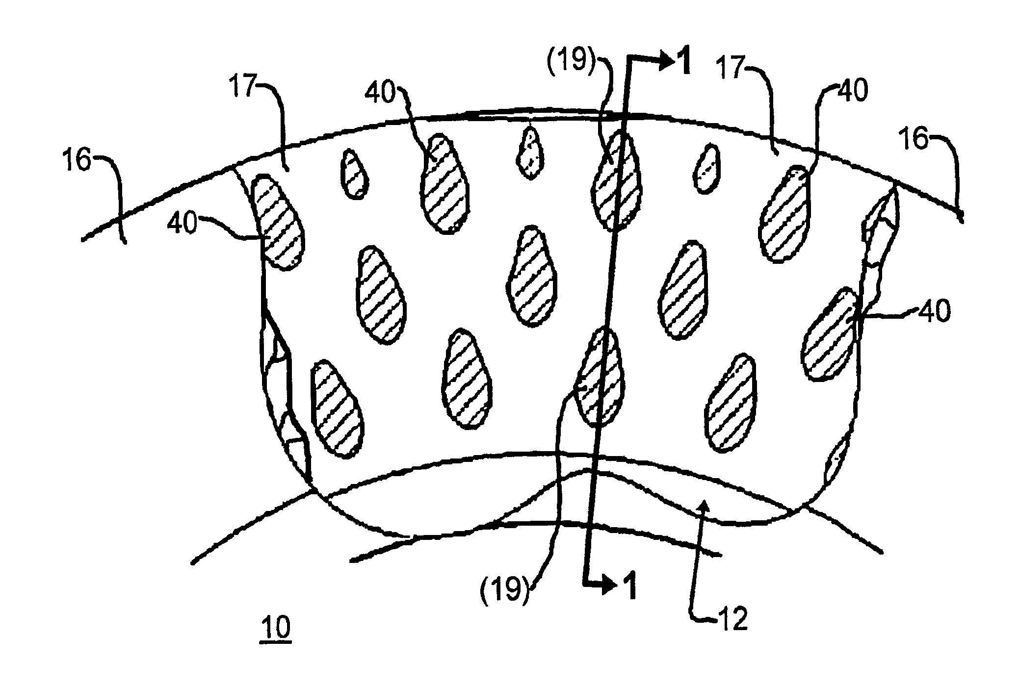
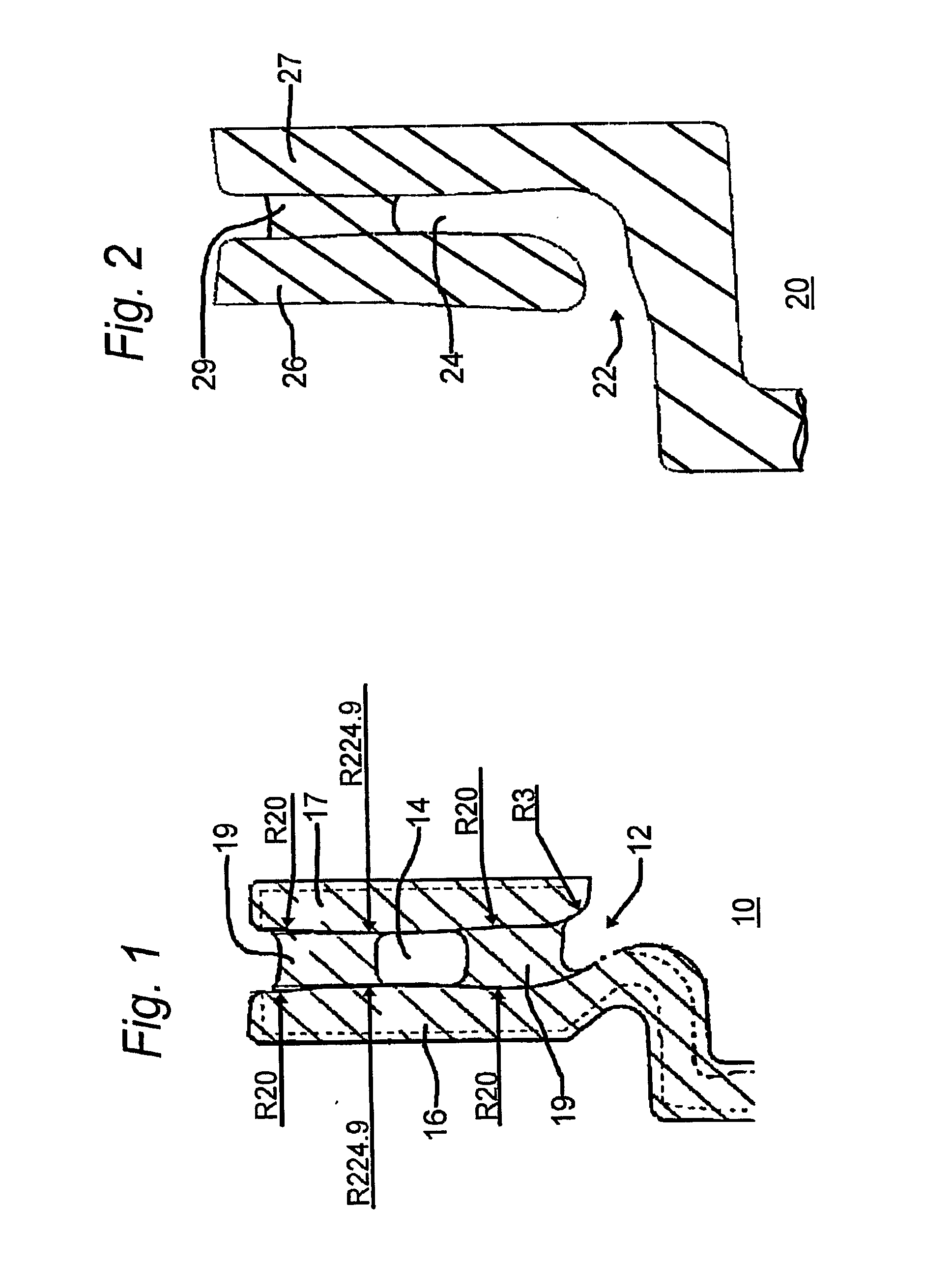
[0032]FIG. 1 is a simplified schematic cross-sectional representation of a disc brake rotor arrangement 10 configured in the characteristic of a venturi nozzle 12 in accordance with the principles of the invention. As shown in this figure, nozzle 12 is arranged at the inlet to ventilated area 14 to create pressure differentials (not shown in this figure) and thereby move air (not shown in this figure) faster. In this manner, an increased amount of air is essentially pumped into ventilated area 14. Ventilated area 14 is shown to be disposed between rotor face plates 16 and 17. More specifically, the interior surfaces of rotor face plates 16 and 17 are, in this specific illustrative embodiment of the invention, both axially inwardly arched with a predetermined curvature whereby the central annular region of ventilated area 14 has a reduced cross-sectional distance relative to the radially inward and outer peripheries. This creates an annular venturi nozzle effect for air that enters t...


PUM


Abstract

A rotor arrangement for the brake system of a vehicle has first and second annular rotor plates substantially in parallel, with a ventilated region therebetween for cooling the rotor plates. A plurality of airfoil-shaped structures is arranged in the ventilated region, each being coupled at one portion thereof to the first rotor plate, and at a second portion thereof to the second rotor plate, to maintain the first and second rotor plates in fixed spatial relation. The first and second rotor plates and the airfoil-shaped pillar structures are integrally formed, the interior surfaces of the rotor plates being configured as an annular venturi that increases the air flow therebetween. The airfoil-shaped structures are configured as airfoil-shaped pillars and fins to form a corresponding plurality of effective venturi nozzles whereby the flow of air between the rotor plates is laminar and increased to enhance the cooling of the annular rotor plates.

Description

BACKGROUND OF THE INVENTION[0001]1. Field of the Invention[0002]This invention relates generally to braking systems for vehicles, and more particularly, to a disc brake rotor having an aerodynamic vent that improves rotor ventilation while achieving ease of manufacture.[0003]2. Description of the Related Art[0004]It is well known that a large amount of heat is produced during the stopping of a vehicle. The heat results from the conversion of kinetic energy, and most of this heat is conducted into the brake rotor, where multiple adverse conditions are thereby generated. These include, for example, the distortion of the rotor face plates and a diminution in friction between the brake caliper pads and the brake rotor.[0005]It is, therefore, an object of this invention to provide a brake rotor arrangement wherein heat is rapidly removed.[0006]It is another object of this invention to provide a ventilated brake rotor arrangement that rapidly transfers heat away from the rotor face plates...

Claims


Application Information

Patent Timeline
IPC IPC(8): F16D65/00
CPCF16D2065/1328F16D65/12
Inventor GONZALEZ-ROCHA, MAURICIO
Owner RASSINI FRENOS S A DE
Why Eureka
Try Eureka