Retarder-based despeckle device for laser illumination systems

Active Publication Date: 2009-10-15
VIAVI SOLUTIONS INC
View PDF11 Cites 75 Cited by
  • Summary
  • Abstract
  • Description
  • Claims
  • Application Information

AI Technical Summary

Benefits of technology

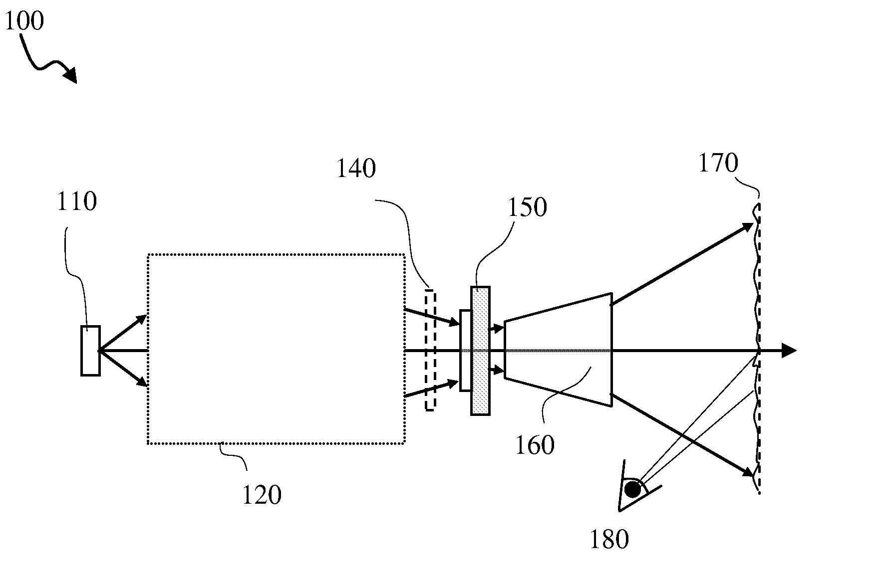
[0009]The instant invention relates to a method of creating many varied boiling speckle patterns using an actuatable waveplate element. In one embodiment, the boiling speckle patterns are presented to a detector (e.g., human eye, photodetector) at the image plane over time, along with the static / variable speckle patterns resulting from index inhomogeneity of optical elements and / or projection screen roughness. These uncorrelated or partially correlated speckle patterns are incoherently summed over the detector integration interval (e.g., are temporally averaged). This temporally averaged speckle pattern reduces the speckle contrast by reducing the deviation of any observation pixel from the required image intensity in the absence of speckle.
[0011]According to one embodiment, the actuatable waveplate element is a waveplate assembly including two or more stages. In the first-stage, a single-layer quarter-waveplate (QWP) or a multiple-layer achromatic (A) QWP is oriented such that it's optic axis (also slow-axis, SA) is aligned at ±π / 4 (45 degrees) azimuthal angle offset to the polarized light output from the laser source. As a result, the linearly polarized light output from the laser is converted from a first linear polarization to a first handedness of circular polarization. In the second stage, a near half-waveplate (HWP) element converts the first circular polarization (i.e., having the first handedness) to a second circular polarization (i.e., having a second opposite handedness). The near HWP has a varied slow axis distribution (e.g., the slow axis orientation varies across the plane of the optical retarder in a predetermined or random pattern). In a third optional stage, a second QWP or AQWP converts the second circular polarization to a second linear polarization. If the retarder axes of the first stage and the third stage QWPs are aligned parallel, the second linear polarization is parallel to the first linear polarization. If however, the two QWP stages are aligned with crossed axes, the first and the second linear polarizations are orthogonal. If the third stage QWP is omitted, circular polarization is output and passed to the appropriate optical modulator (e.g., having a plurality of micromirrors). Notably, this polarization transformation forms a closed loop locus on the Poincare Sphere to induce a geometric phase shift dependent on the optic axis orientation of the second stage near HWP. Since the near HWP includes a varied optic axis distribution, this waveplate assembly functions as a despeckle device, which imposes a spatially and / or temporally varied phase mask upon the coherent laser beam, thus reducing the perceived speckle, while still maintaining a high degree of input power in the required output polarization state.
[0012]In accordance with one aspect of the instant invention there is provided a method of reducing speckle in a laser illumination system comprising: inserting a despeckle device in a beam of light, the beam of light including light emitted from a coherent laser in the laser illumination system, the despeckle device including an optical retarder for providing an odd integer multiple of substantially half-wave retardation for the light emitted from the coherent laser, the optical retarder having a substantially constant retardance and a spatially varied slow axis, the spatially varied slow axis for imposing a phase mask on the beam of light, the phase mask for providing sub-resolution optical phase modulation to a resolution spot on a detector; and actuating the optical retarder such that the sub-resolution optical phase modulation is varied within an integration time of the detector and such that an intensity non-uniformity of one detected resolution spot to another is reduced.
[0013]In accordance with another aspect of the instant invention there is provided an apparatus for reducing speckle in a laser illumination system comprising: a despeckle device including an optical retarder for providing an odd integer multiple of substantially half-wave retardation for light emitted from a coherent laser in the laser illumination system, the optical retarder having a substantially constant retardance and a spatially varied slow axis, the spatially varied slow axis for imposing a phase mask on a beam of light, the beam of light including the light emitted from the coherent laser, the phase mask for providing sub-resolution optical phase modulation to a resolution spot on a detector; and an actuator for actuating the optical retarder such that the sub-resolution optical phase modulation is varied within an integration time of the detector and such that an intensity non-uniformity of one detected resolution spot to another is reduced.

Problems solved by technology

However, while lasers provide bright images with good color, the image quality can be degraded due to speckle.
More specifically, it arises when the reflected light, which includes multiple beams with differential delays greater than the wavelength of light, interfere at the detector (e.g. human eye, or square law photodetector).
The resulting random spatial interference of the reflected laser light produces a speckle pattern that significantly degrades the quality of the image (e.g., making it appear grainy and / or less sharp).
In addition, depending on the view point, the speckle pattern may change due to the different characteristics of relative phase delays in a given direction.
As a result, the image being observed changes with view point and the optical system fails to reliably recreate a high fidelity image.
Unfortunately, this approach is expensive, and is not always practical, since many miniature projectors rely on a single LD chip to output tens of lumens illumination.
Generally, this approach is bulky and has limited speckle contrast reduction.
In addition, it is not ideal if the laser coherence length is very long.
Unfortunately, for a large projection screen, this is not very practical.
While the more commonly used methods of creating many varied boiling speckle patterns to provide temporal averaging have been reasonably successful at reducing spectral contrast, they have been generally limited by the surface pattern physically etched / embossed in prior art diffusers / phase plates.
For example, these raised surface patterns have been shown to significantly degrade the quality of the laser beam.

Method used


Image

  • Retarder-based despeckle device for laser illumination systems
  • Retarder-based despeckle device for laser illumination systems
  • Retarder-based despeckle device for laser illumination systems

Examples


Embodiment Construction

[0061]A laser-based projector (PJ) system is illustrated in FIG. 1. In this system 100, the output light from the light source 110 is homogenized and shaped by optical elements 120 in order to form a rectangle of uniform illumination at the required aspect ratio on the display panel 150. In this embodiment, the light source 110 includes one co-packaged Red, Green and Blue (RGB) laser diode (LD) module. In other embodiments, the light source includes three discretely coupled RGB LDs. The beam shaping optics 120, which in one embodiment include a high performance lightpipe, collimation lenses, or fly's eye array, will also typically include polarization conversion and / or recovery optics if the display panel 150 uses polarization modulation (e.g., liquid crystal based display). In other embodiments (e.g., for space-constrained nano / pico-projectors), the beam shaping optics 120 includes a combination of diffractive / refractive flat optics used to homogenize and shape the rectangle in the...


PUM


Abstract

A method and apparatus for reducing speckle in a laser illumination system uses a despeckle device including an optical retarder providing an odd integer multiple of substantially half-wave retardation for light emitted from a coherent laser in the laser illumination system. The near half-wave optical retarder has a substantially constant retardance and a spatially varied slow axis. The spatially varied slow axis imposes a phase mask on the beam of light, which provides sub-resolution optical phase modulation to a resolution spot on the detector. The near half-wave optical retarder is actuated mechanically or electrically to vary the sub-resolution optical phase modulation within an integration time of the detector.

Description

CROSS-REFERENCE TO RELATED APPLICATIONS[0001]This application claims priority from U.S. Provisional Application No. 60 / 045,012, filed Apr. 15, 2008, which is hereby incorporated by reference for all purposes.TECHNICAL FIELD[0002]The present application relates generally to speckle reduction, and in particular, to a retarder-based method and apparatus for reducing speckle in laser illumination systems.BACKGROUND OF THE INVENTION[0003]Laser illumination systems are commonly used in projection displays to provide high power illumination and saturated color. However, while lasers provide bright images with good color, the image quality can be degraded due to speckle.[0004]Speckle arises when coherent light is reflected from a rough or dusty surface, or propagates through a medium with random refractive index variations. More specifically, it arises when the reflected light, which includes multiple beams with differential delays greater than the wavelength of light, interfere at the dete...

Claims


Application Information

Patent Timeline
IPC IPC(8): G02B27/48G02F1/03
CPCG02B27/286G02B27/48Y10S359/90H04N9/3161H04N9/3197H04N9/3126G02B27/18
Inventor TAN, KIM L.SHEMO, DAVID M.MCELDOWNEY, SCOTT
Owner VIAVI SOLUTIONS INC
Why Eureka
Try Eureka