
Ratcheting mechanical driver for cannulated surgical systems

a technology of mechanical driver and cannulated surgical system, which is applied in the field of apparatus and method for manipulating cannulated surgical tool, can solve the problems of restricting user's movement, and affecting the use of the user's movemen

Inactive Publication Date: 2009-10-08
PIONEER SURGICAL TECH INC
View PDF26 Cites 274 Cited by
  • Summary
  • Abstract
  • Description
  • Claims
  • Application Information

AI Technical Summary

Benefits of technology

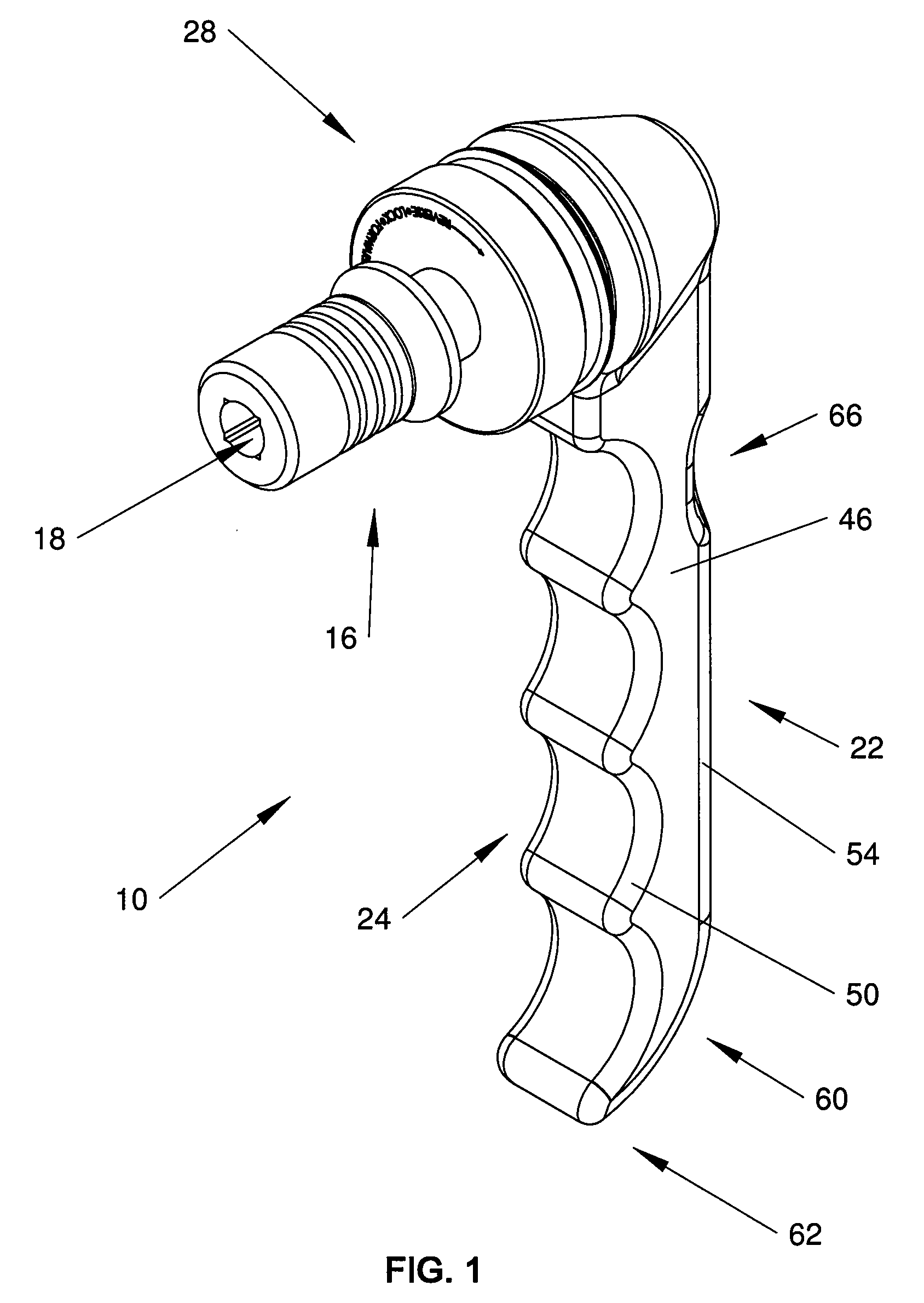
[0012]In accordance with one aspect of the invention, a device for rotatably driving a cannulated tool along a guide wire is provided that allows a user to exert a rotary force to the cannulated tool via an elongate gripping portion positioned away from the guide wire. In this regard, the device has an elongate coupling assembly with an axial through bore in which the tool and the guide wire extending through the tool are received. The device has a handle assembly for rotatably driving the tool, the handle assembly including an end portion connected to the coupling assembly. Positioned between the handle assembly and the coupling assembly is a ratchet mechanism configured so that turning the handle assembly in one rotary direction turns the coupling assembly therewith. The coupling assembly is also configured so that the handle assembly turns relative to the coupling assembly in an opposite rotary direction. Additionally, the device includes an elongate gripping portion of the handle assembly extending transversely to the coupling assembly. By grasping the handle assembly gripping portion, a user may exert a levered mechanical advantage for turning the coupling assembly and cannulated tool received therein.
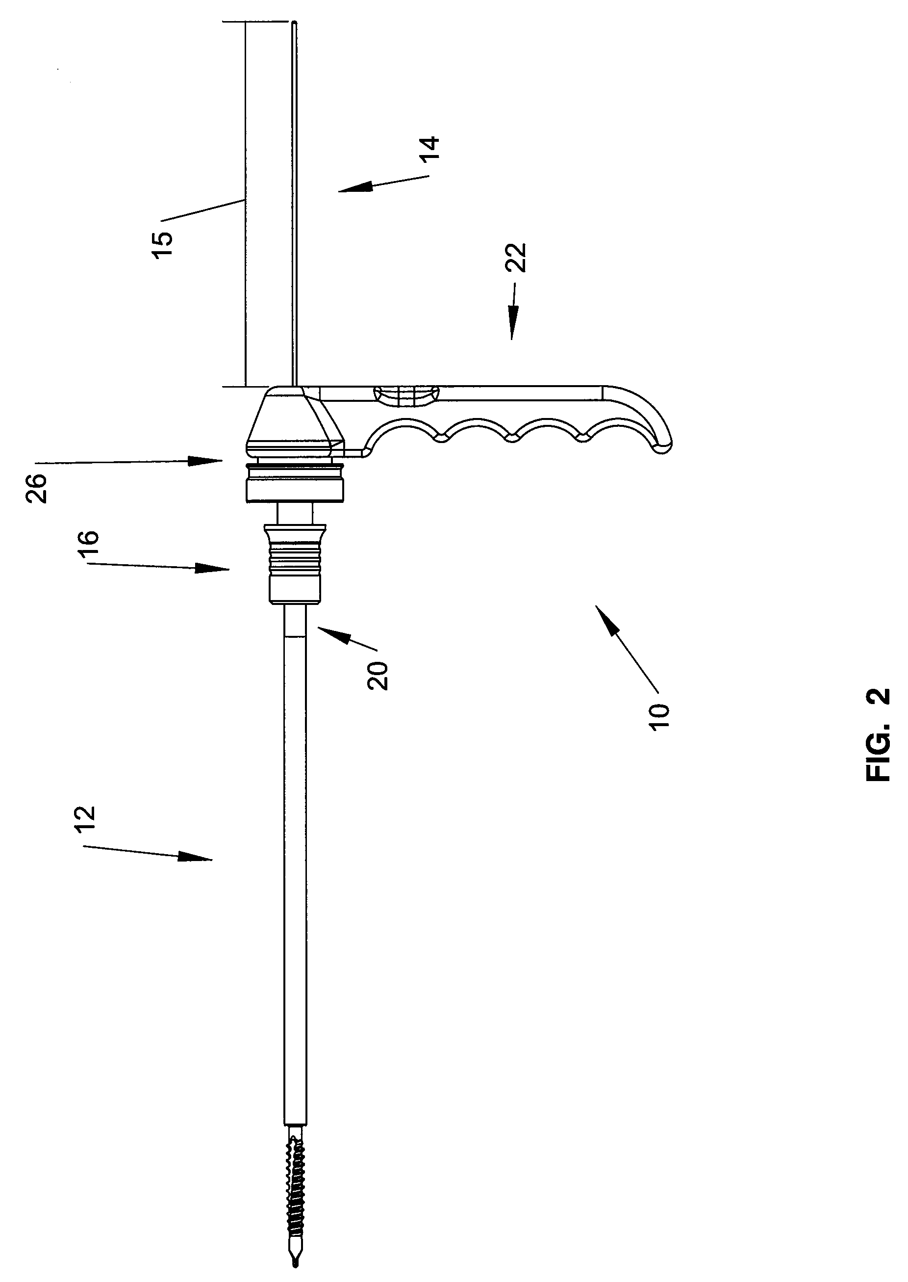
[0014]The connection assembly is attached to the handle coupling end portion so that the through bores of the connection assembly and the transverse handle are coaxial. The through bore of the handle coupling end portion is relatively short compared to the length of the connection assembly through bore. Specifically, the through bore of the handle coupling end portion is shorter than the connection assembly through bore as measured along the connection assembly through bore from the end in communication with the socket opening to the upper surface of the handle. Accordingly, the mechanical driver limits the length of the connection assembly through bore that overlies the guide wire extending beyond the cannulated tool. This permits the use of shorter guide wires while preserving the ability to visually monitor the position of the guide wire relative to the cannulated tool.

Problems solved by technology

It has been observed, however, that the cannula of the tool may become obstructed during use which causes the tool to bind to the guide wire.
If the cannulated tool and guide wire become bound together, driving the tool into the vertebra may cause the guide wire to be driven through the vertebral body and into harmful contact with the structures of the circulatory or nervous systems.
Despite the benefits of using a guide wire with cannulated tools, the guide wire is often problematic in that the presence of the guide wire extending beyond the tool may restrict the user's movement.
This positioning tends to limit the ability to visually monitor the length of the guide wire projecting beyond the cannulated tool.
Additionally, the guide wire may potentially puncture the glove or hand of the user, especially if the end of the guide wire is sharp.
Prior attempts to remedy these shortcomings fail to provide sufficient mechanical advantage and operability such that a user may quickly and efficiently engage or disengage the cannulated tool with the bone.

Method used


Image

  • Ratcheting mechanical driver for cannulated surgical systems
  • Ratcheting mechanical driver for cannulated surgical systems
  • Ratcheting mechanical driver for cannulated surgical systems

Examples


Embodiment Construction

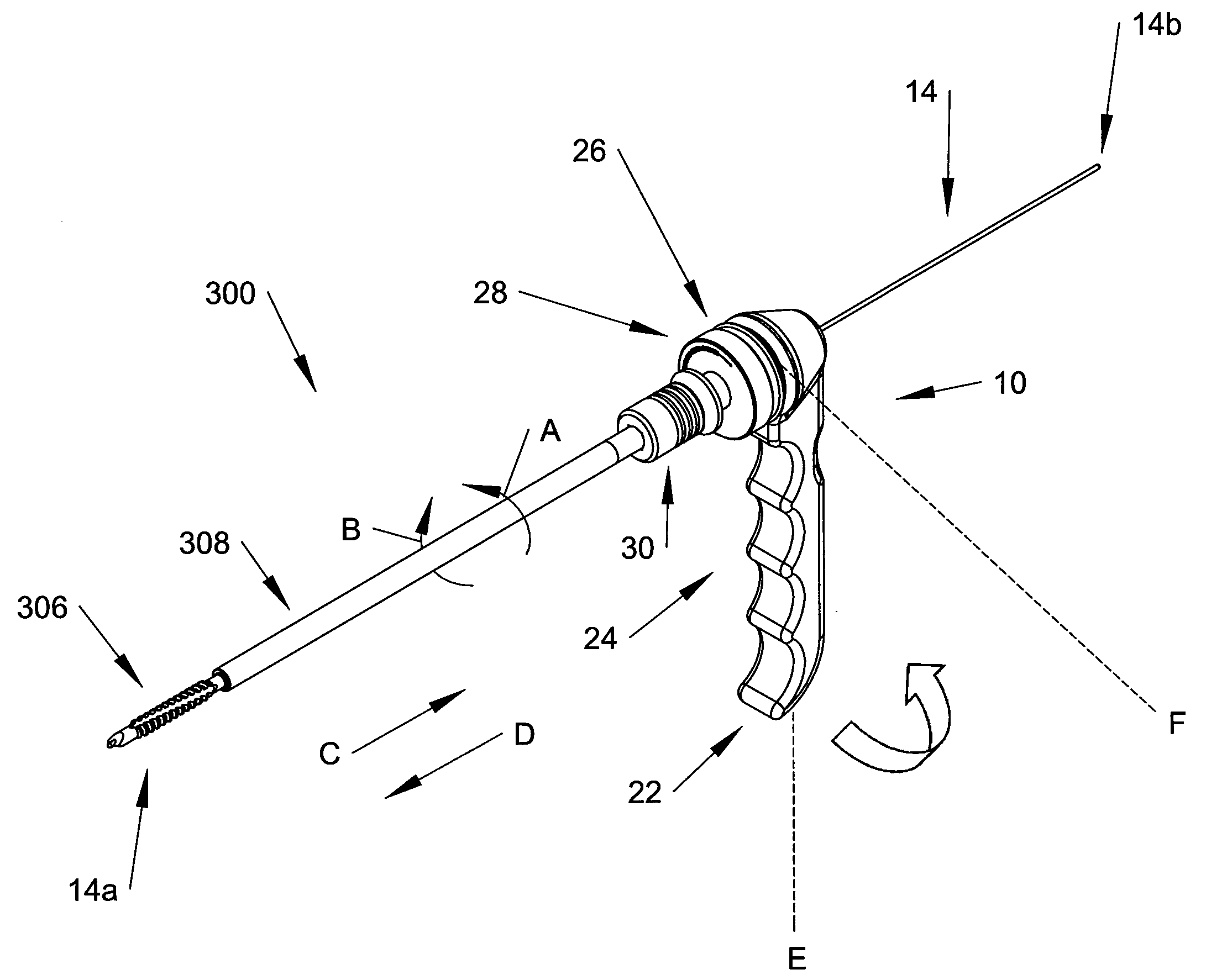
[0029]In FIGS. 1 and 2, a device in the form of a mechanical driver 10 for rotatably driving a cannulated tool 12 along a guide wire 14 is shown. The mechanical driver 10 has a coupling assembly 16 with a through bore 18 for receiving an end 20 of the cannulated tool 12 and a guide wire 14 extending therethrough. A handle assembly 22 having an elongate gripping portion 24 extends transversely to the coupling assembly 16. The coupling assembly 16 is configured to quickly and releasably engage the end 20 of a variety of different tools. Additionally, the mechanical driver 10 is configured to permit the guide wire 14 to pass through the coupling assembly 16 and beyond the handle assembly 22.

[0030]During an operation, a guide wire 14 is placed adjacent a bone surface to guide the cannulated tool 12 into contact with the bone. Then, the mechanical driver 10 is connected to the cannulated tool 12 before sliding the tool 12 along the guide wire 14. The handle assembly 22 spaces the user's ...


PUM


Abstract

A device for rotatably driving a cannulated tool along a guide wire. In one aspect, the device includes a coupling assembly for receiving the tool and guide wire as well as a ratchet mechanism permitting selective rotation between the device and the tool. The device further includes an elongate gripping portion extending transversely to the coupling assembly to provide a levered mechanical advantage while positioning the gripping portion out of the path of the guide wire. In another aspect, the device includes a handle having a through bore shorter than a predetermined length of a connection assembly through bore so that only a short portion of the guide wire is covered by the device. A method of driving a cannulated tool along a guide wire is also provided that includes rotating a gripping portion of a handle assembly about the tool in an arcuate path spaced from the tool.

Description

CROSS-REFERENCE To RELATED APPLICATIONS[0001]This application claims the benefit of U.S. Provisional Patent Application Ser. No. 61 / 043,206, filed Apr. 8, 2008, which is hereby incorporated by reference as if fully set forth herein.FIELD OF THE INVENTION[0002]The invention relates to an apparatus and method for manipulating a cannulated surgical tool and, more particularly, to a device having a ratchet mechanism for selectively permitting rotation of the surgical tool relative to the device.BACKGROUND OF THE INVENTION[0003]Implant devices secured to bone or bone segments are utilized to promote the healing and repair of various parts of the human body. In some cases, the implant devices are secured to the bone or bone segments such that the bones themselves heal, fuse, or stabilize relative to one another. In other cases, implant or fixation devices are used to secure bones or bone fragments so that the surrounding soft tissue may heal without disruption by relative movement of the ...

Claims


Application Information

Patent Timeline
IPC IPC(8): A61B17/58
CPCA61B17/1637A61B2017/00473A61B2017/00469
Inventor KNAPP, TROY D.BERMAN, PHILLIP J.
Owner PIONEER SURGICAL TECH INC
Learn More