
Membrane/electrode assembly for polymer electrolyte fuel cells and polymer electrolyte fuel cell

a technology of electrolyte fuel cells and electrolyte fuel cells, which is applied in the direction of fuel cells, fuel cell details, solid electrolyte fuel cells, etc., can solve the problems of poor handling efficiency, prone to swelling and shrinkage, and polymer electrolyte membranes are likely to break, etc., to achieve sufficient mechanical strength and dimensional stability, high power generation performance, and excellent durability

Active Publication Date: 2009-10-01
ASAHI GLASS CO LTD
View PDF9 Cites 60 Cited by
  • Summary
  • Abstract
  • Description
  • Claims
  • Application Information

AI Technical Summary

Benefits of technology

[0019]The present invention is to provide a membrane / electrode assembly for polymer electrolyte fuel cells which is capable of providing high power generation performance even under a low humidity condition and has sufficient mechanical strength and dimensional stability and which has excellent durability even under an environment where moistening, drying, etc. are repeated, and to provide a polymer electrolyte fuel cell which is capable of power generation even under a low humidity condition and whereby a peripheral device such as a humidifying device can be simplified.
[0036]The membrane / electrode assembly for polymer electrolyte fuel cells of the present invention is capable of providing high power generation performance even under a low humidity condition and has sufficient mechanical strength and dimensional stability, and it has excellent durability even in an environment where moistening, drying, etc. are repeated.
[0037]The polymer electrolyte fuel cell of the present invention is capable of constant power generation even under a low humidity condition, whereby a peripheral device such as a humidifying device can be simplified, and it is thus advantageous for reduction of the size and the costs.

Problems solved by technology

In a case where the dimensional stability or the mechanical strength of the membrane / electrode assembly is low, the handling efficiency is likely to be poor in assembling the cell, or the polymer electrolyte membrane is likely break during its operation.
However, the polymer electrolyte membrane has such a nature that as EW is smaller, it tends to undergo swelling and shrinkage due to changes of the humidified environment.
Consequently, the polymer electrolyte membrane will get wrinkles.
And, in a case where the thickness of the polymer electrolyte membrane is thin, the polymer electrolyte membrane may break due to such wrinkles.
However, the composite membrane (1) has such a problem that as compared with a membrane not reinforced, the ion conductivity tends to be low, and the power generation performance tends to be low particularly under a low humidity condition.
The composite membrane (2) also has a problem such that when a porous material having sufficient chemical stability and mass productivity is selected for use, the ion conductivity tends to be low as compared with the membrane not reinforced, and the power generation performance tends to be low particularly under a low humidity condition.
In the case of the membrane / electrode assembly (3), the dimensional stability and mechanical strength are still inadequate, and it is not durable against the above-mentioned repetition of swelling and shrinkage especially when the thickness of the polymer electrolyte membrane is at most 25 μm.

Method used


Image

  • Membrane/electrode assembly for polymer electrolyte fuel cells and polymer electrolyte fuel cell
  • Membrane/electrode assembly for polymer electrolyte fuel cells and polymer electrolyte fuel cell
  • Membrane/electrode assembly for polymer electrolyte fuel cells and polymer electrolyte fuel cell

Examples


examples

[0274]Now, the present invention will be described in further detail with reference to Examples. However, it should be understood that the present invention is by no means thereby restricted.

[0275]Examples 1 to 5, 9 to 16 and 18 to 21 are Examples of the present invention, and Examples 6 to 8 and 17 are Comparative Examples.

[0276]EW

[0277]EW of the polymer (P) was obtained by the following method.

[0278]Two types of polymers, of which EW is preliminarily known by titration (one having EW of 1,000 g / equivalent, and one having EW of 909 g / equivalent) were prepared, and with respect to two types of membranes made of the respective polymers (thickness: 200 μm), the peak intensities based on sulfur atoms were measured by means of fluorescent X-ray (RIX3000, manufactured by Rigaku Corporation), whereupon a calibration curve showing the relation between the peak intensity and EW was prepared. The polymer (P) was pressed at a temperature of the after-mentioned TQ value to prepare a membrane h...

preparation example

[0307]By the following synthesis route, the compound (m12) was prepared.

Preparation of Compound (a2)

[0308]The compound (a2) was prepared in the same manner as the method disclosed in Example 2 in JP-A-57-176973.

Preparation of Compound (c2)

[0309]Into a 300 cm3 four-necked round-bottomed flask equipped with a Dimroth condenser, a thermometer, a dropping funnel and a glass rod with stirring vanes, 1.6 g of potassium fluoride (CHLOROCATCH F, manufactured by Morita Chemical Industries Co., Ltd.) and 15.9 g of dimethoxyethane were charged in a nitrogen atmosphere. Then, the round-bottomed flask was cooled in an ice bath, and 49.1 g of the compound (b11) was dropwise added from the dropping funnel over a period of 32 minutes at an internal temperature of at most 10° C. After completion of the dropwise addition, 82.0 g of the compound (a2) was dropwise added over a period of 15 minutes from the dropping funnel. No substantial increase in the internal temperature was observed. After completi...

example 1

Step (I)

Preparation of Polymer (P1)

[0316]An autoclave (internal capacity: 2,575 cm3, made of stainless steel) was flushed with nitrogen and sufficiently deaerated. Under reduced pressure, 950.3 g of the compound (m12), 291.4 g of the compound (m21), 490.1 g of the compound (3-1) as a solvent, 173.7 mg of methanol and 873.1 mg of the compound (4) (Peroyl IPP, manufactured by NOF Corporation) as a radical initiator, were charged, and inside of the autoclave was deaerated to vapor pressure.

CClF2CF2CHClF  (3-1)

(CH3)2CHOC(═O)OOC(═O)OCH(CH3)2  (4)

[0317]The internal temperature was raised to 40° C., and TFE was introduced into the autoclave to adjust the pressure to 0.44 MPaG (gauge pressure). While the temperature and the pressure were maintained to be constant, polymerization was carried out for 6.0 hours. Then, inside of the autoclave was cooled to terminate the polymerization, and the gas in the system was purged.

[0318]The reaction liquid was diluted with the compound (3-1), and then, ...


PUM

PropertyMeasurementUnit
lengthaaaaaaaaaa
diameteraaaaaaaaaa
pore diameteraaaaaaaaaa

Abstract

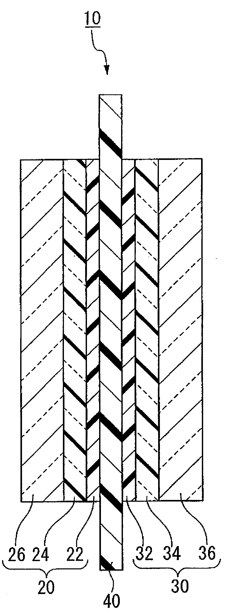
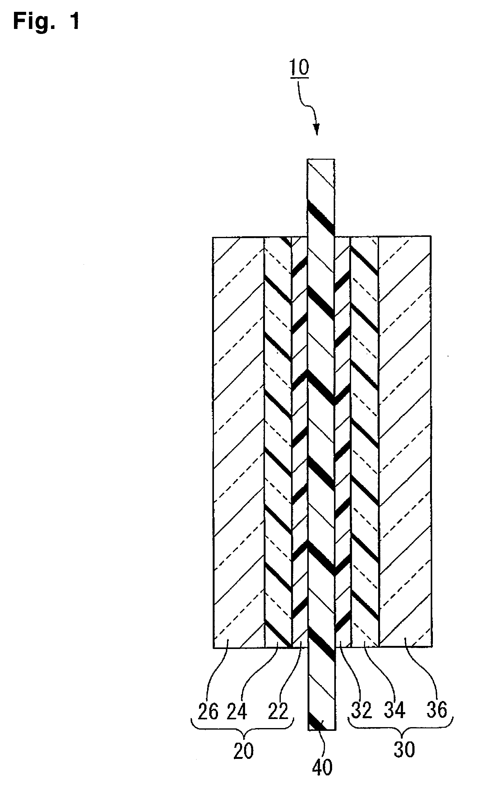
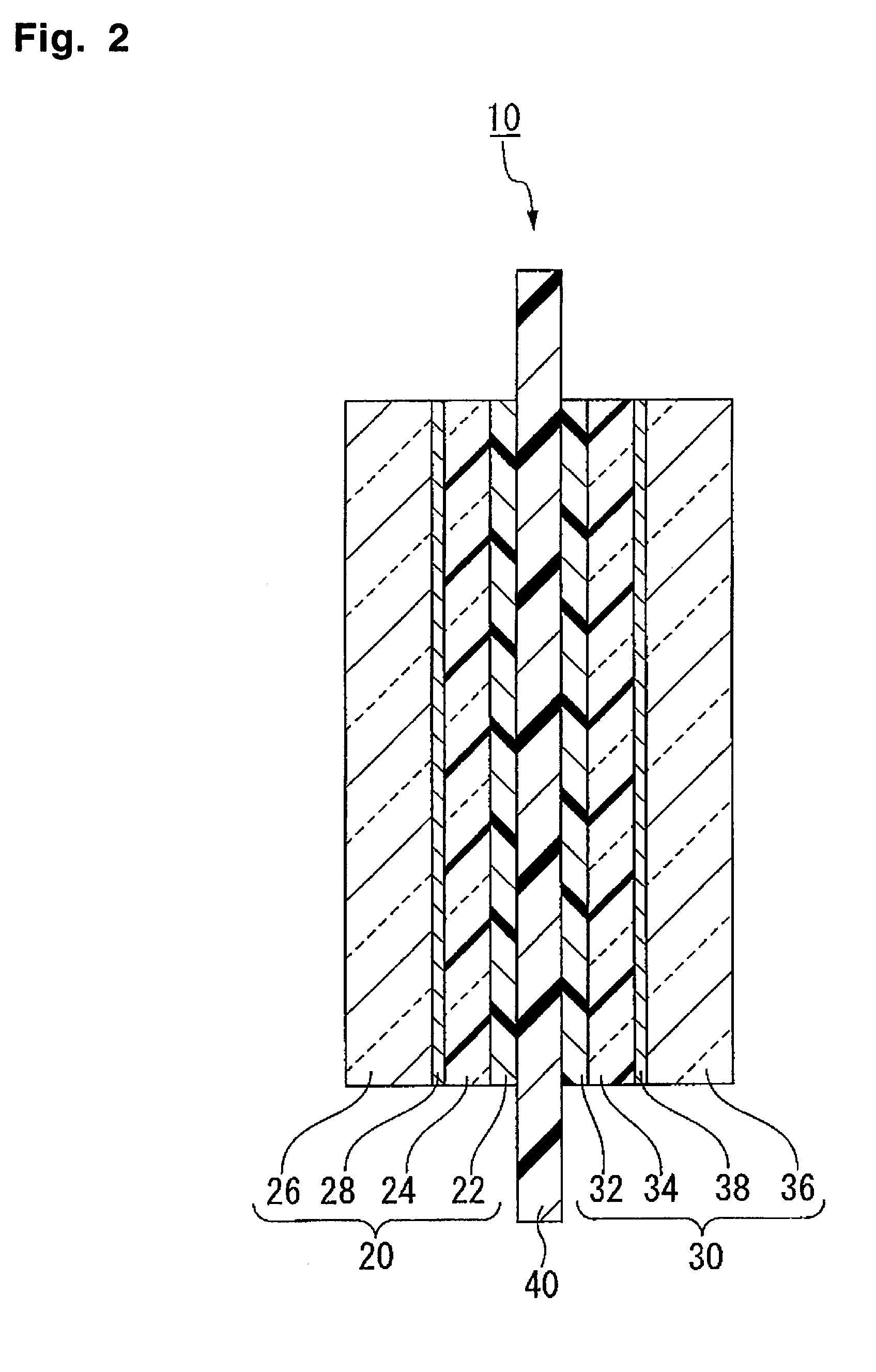
To provide a membrane / electrode assembly for polymer electrolyte fuel cells, which is capable of providing high power generation performance even under a low humidity condition and has sufficient mechanical strength and dimensional stability, and which has an excellent durability even in an environment where moistening and drying are repeated, and a polymer electrolyte fuel cell which is capable of providing high power generation performance even under a low humidity condition.A membrane / electrode assembly 10 is used, which comprises a cathode 20 having a catalyst layer 22, an anode 30 having a catalyst layer 32, and a polymer electrolyte membrane 40 interposed between the catalyst layer 22 of the cathode 20 and the catalyst layer 32 of the anode 30, wherein at least one of the cathode 20 and the anode 30 further has a reinforcing layer 26 comprising a porous sheet-form reinforcing material made of a polymer, and an electrically conductive fiber.

Description

BACKGROUND OF THE INVENTION[0001]1. Field of the Invention[0002]The present invention relates to a membrane / electrode assembly for polymer electrolyte fuel cells, and a polymer electrolyte fuel cell.[0003]2. Discussion of Background[0004]Fuel cells are expected to be widely used, since is their power generation efficiency is high, the reaction product is only water in principle, and the load to the environment is small. Among them, a polymer electrolyte fuel cell has a high output density and is therefore expected to be widely used as an automobile or distributed power generation system, a portable power generation system for a household cogeneration system.[0005]A polymer electrolyte fuel cell is usually constituted by a cell wherein an electrically conductive separator having gas flow paths formed, is disposed on each side of a membrane / electrode assembly comprising a cathode having a catalyst layer and a gas diffusion layer, an anode having a catalyst layer and a gas diffusion la...

Claims


Application Information

Patent Timeline
Patent Type & Authority Applications(United States)
IPC IPC(8): H01M8/10
CPCH01M8/0291H01M8/0297H01M8/1004H01M8/1023Y02E60/521H01M8/106H01M8/1062H01M8/1067H01M8/1039H01M8/0289Y02E60/50H01M8/0273
Inventor KINOSHITA, SHINJI
Owner ASAHI GLASS CO LTD
Learn More