Diagnostic method for detecting control valve component failure
- Summary
- Abstract
- Description
- Claims
- Application Information
AI Technical Summary
Benefits of technology
Problems solved by technology
Method used
Image
Examples
Embodiment Construction
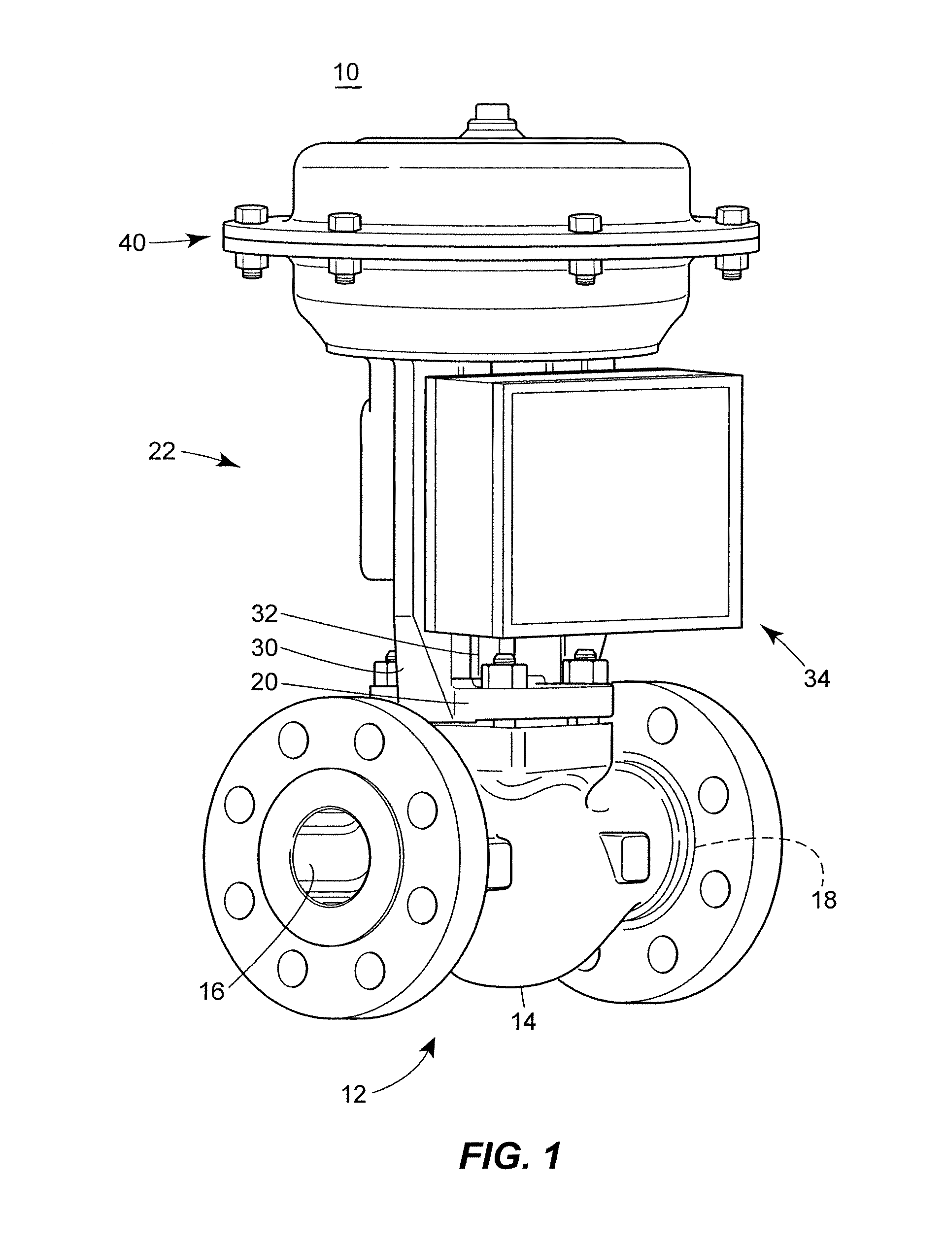
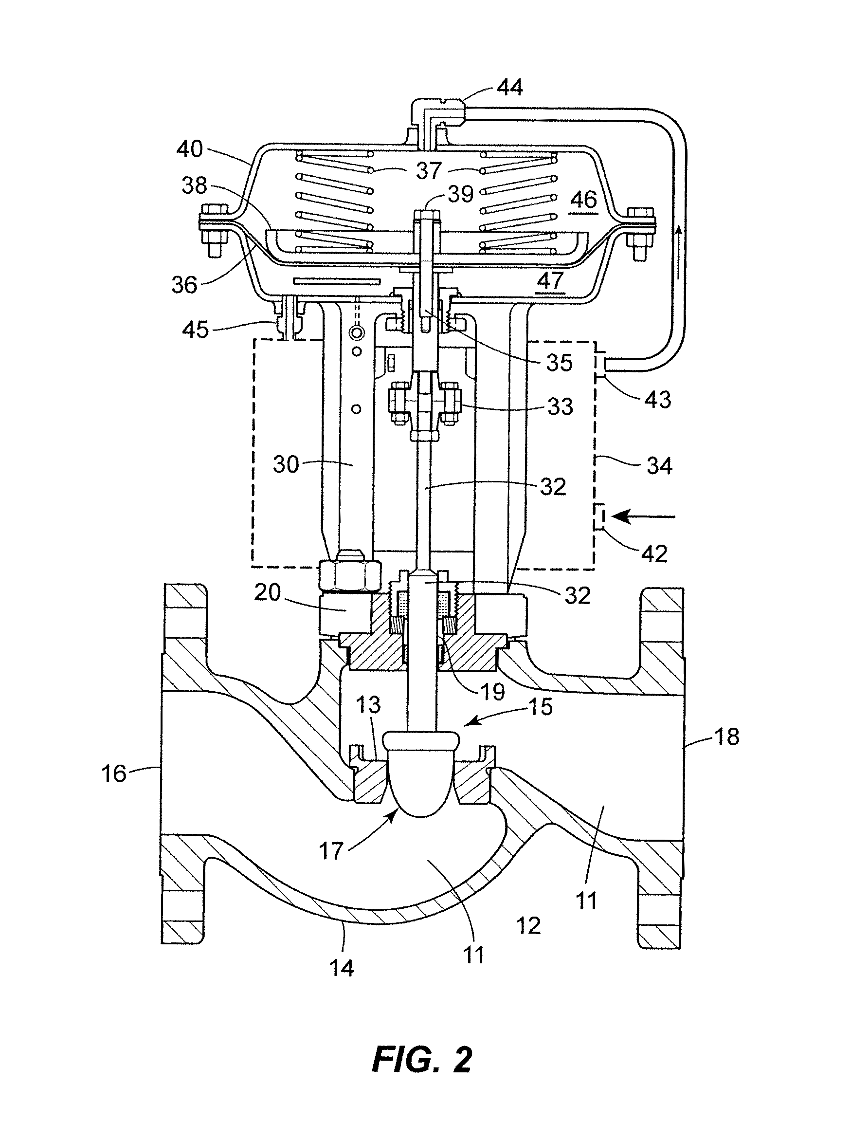
[0023]FIG. 1 illustrates a control valve assembly 10 that may be used in a process control system, e.g., a processing plant. The control valve assembly 10 includes a valve 12, an actuator 22, and a control valve instrument or positioner 34. The valve 12 includes a valve body 14, an inlet port 16, an outlet port 18, and the actuator 22 includes a valve bonnet 20 and pneumatic diaphragm casing 40. Disposed through the valve bonnet 20 may be a valve stem 32 that may be used to operate the valve 12. A yoke 30 may be attached to or provided with the bonnet 20. While the yoke 30 may be connected to the valve bonnet 20, as illustrated in FIG. 1, the yoke 30 may be mounted to another part of the valve body 14 in other embodiments. The yoke 30 may be used to couple the pneumatic diaphragm casing 40 to the valve body 14. The valve stem 32, which may form a portion of a valve stem assembly 15, described further below, may be adapted to transmit force from the pneumatic diaphragm casing 40 to t...
PUM
 Abstract
Description
Claims
Application Information
 - R&D
- Intellectual Property
- Life Sciences
- Materials
- Tech Scout
- Unparalleled Data Quality
- Higher Quality Content
- 60% Fewer Hallucinations
Browse by: Latest US Patents, China's latest patents, Technical Efficacy Thesaurus, Application Domain, Technology Topic, Popular Technical Reports.
© 2025 PatSnap. All rights reserved.Legal|Privacy policy|Modern Slavery Act Transparency Statement|Sitemap|About US| Contact US: help@patsnap.com


