
Rotary gear pump for use with non-lubricating fluids

a non-lubricating fluid and gear pump technology, applied in the field of rotary pumps, can solve the problems of large and expensive maintenance of the pump, poor lubrication properties of the teg, and inability to offer precise transfer applications, etc., and achieve the effect of low friction coefficien

Inactive Publication Date: 2009-08-20
GARRETT RICHARD H
View PDF20 Cites 19 Cited by
  • Summary
  • Abstract
  • Description
  • Claims
  • Application Information

AI Technical Summary

Benefits of technology

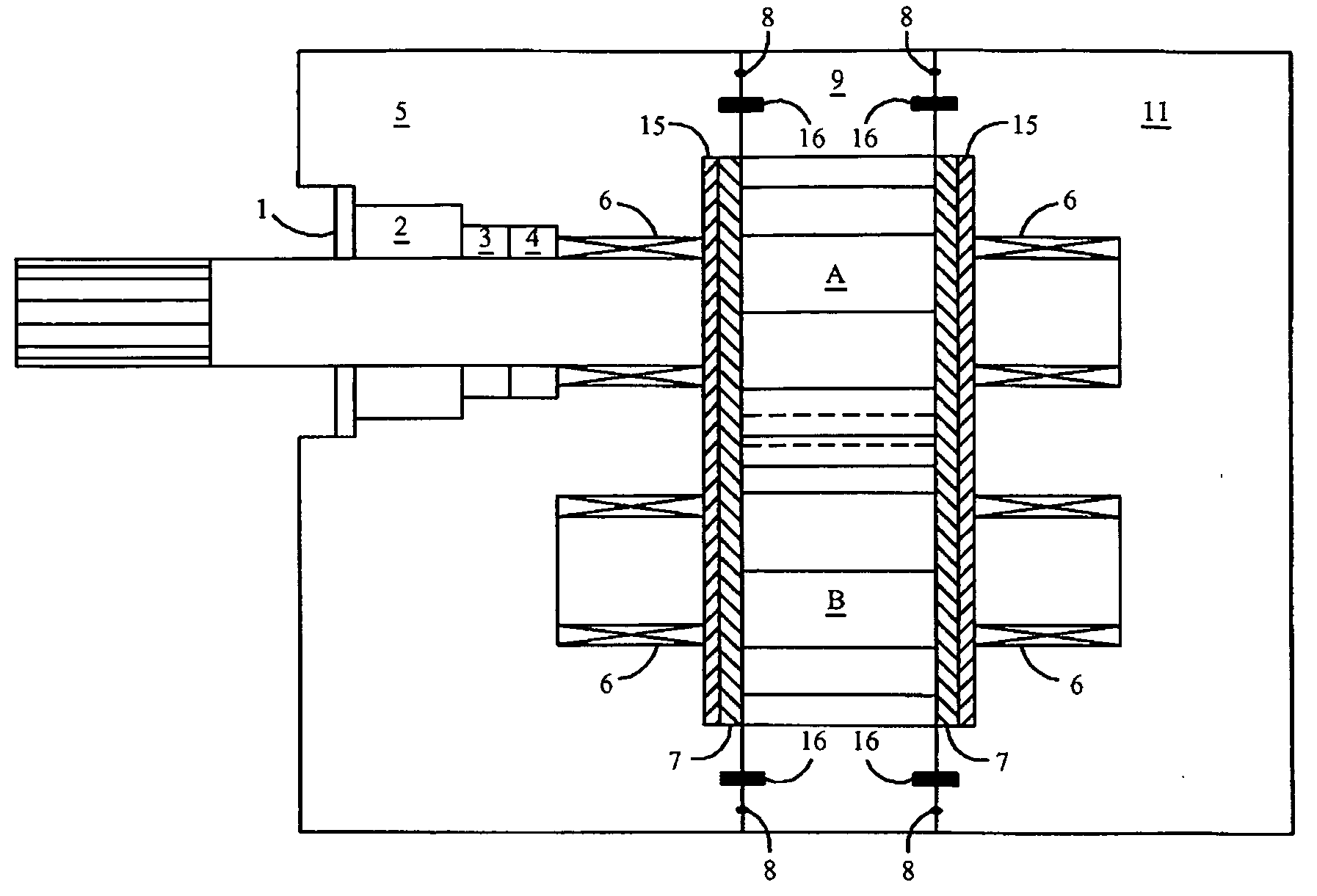
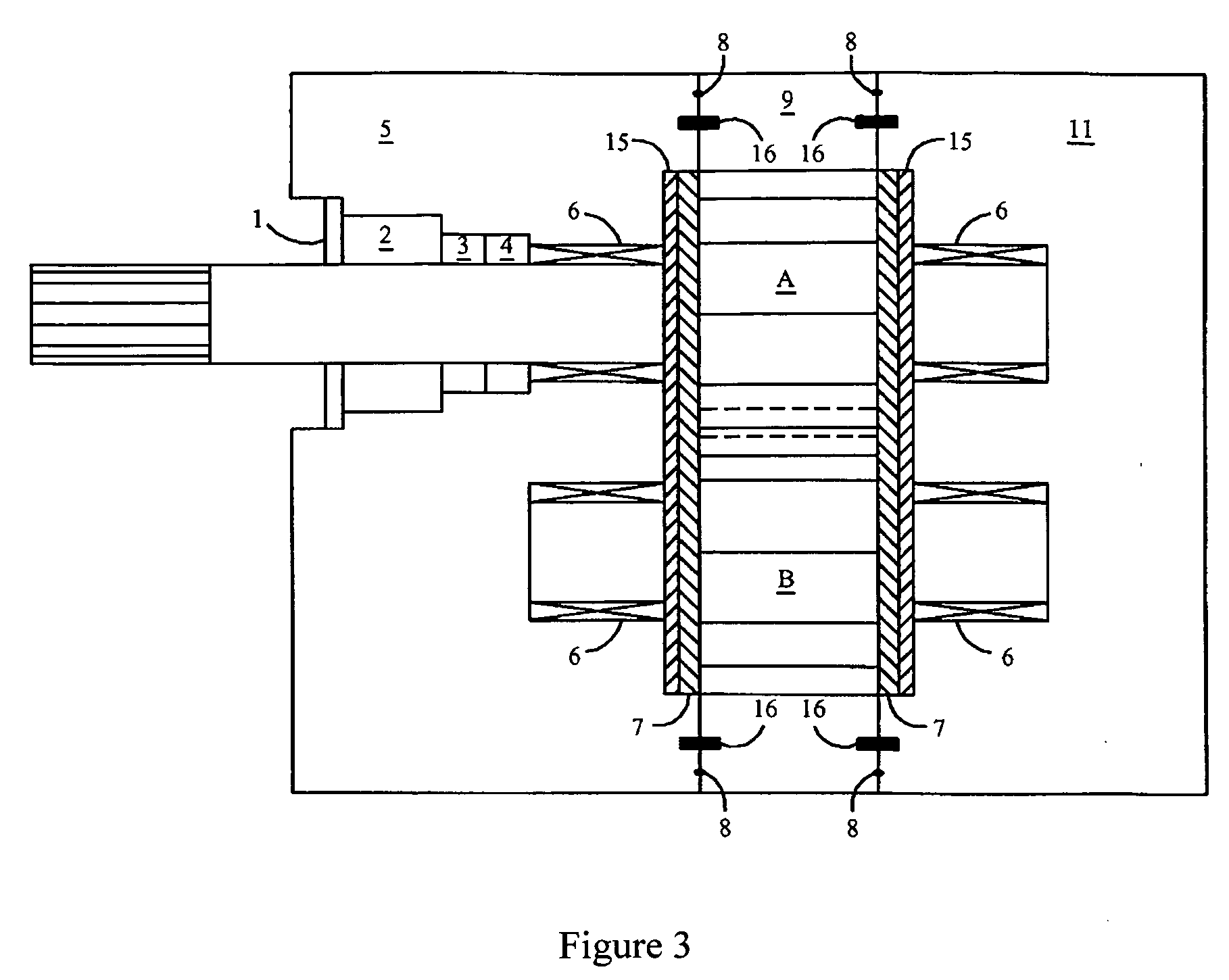
[0029]The instant invention comprises the standard casing employed in a Rotor-Tech external gear pump including standard “DU-Bushings” (essentially a sintered bronze bearing with lead and TFE which is manufactured by the Garlock Company) found in its TEG pumps. A high quality alloy steel (such as carburized 8620) is used in the drive gear and shaft and in the idler gear (similar to the TEG pumps); however, these particular rotating parts are face coated with high technology materials such as “Tungsten-Carbide-Carbon” (WCC) or “Diamond-Like-Carbon” (DLC) in order to provide, the necessary resistance to wear or a propriety combination of the two ceramics. A secondary benefit is that these coatings offer a low coefficient of friction between the meshing gears thereby making up for the poor lubricating properties of amines.

Problems solved by technology

However, unlike external gear pumps, they do not offer precise transfer applications and find little application for polymers, fuels, and expensive liquids.
The industry can use standard piston pumps with pulsation dampers as the prime mover for TEG in the dehydration process; however, these pumps are large and expensive to maintain.
TEG has such poor lubrication properties; nonetheless, industry has found that carefully crafted external gear pumps may be used in TEG service.
Unfortunately amines have even poorer lubrication properties than glycols and rotary gear pumps will wear rapidly when used in amine service.
There have been attempts to produce gear pumps for amine service, however as stated earlier the service life was extremely short because the drive and idler gears would wear prematurely.
Thus, the industry currently uses plunger pumps which are somewhat unreliable.
Some attempts have been made to use gear pumps in amine service, but the driven gear / idler gear system was not used.
There is little guidance in the prior art when it come to pumping non-lubricating fluids.
The action of high viscosity materials increases the loading on shafts and bearings which in the prior art resulted in premature wear.

Method used


Image

  • Rotary gear pump for use with non-lubricating fluids
  • Rotary gear pump for use with non-lubricating fluids
  • Rotary gear pump for use with non-lubricating fluids

Examples


Embodiment Construction

[0034]The inventor serves as the CEO of Rotor-Tech®, Inc. which manufactures an external rotary gear pump for use with a low-lubricating fluid such as glycol. In particular, the inventor was the engineer who oversaw the development of the manufactureable device covered by U.S. Pat. No. 4,511,378 to Greene and has added innovations to the industry in his U.S. Pat. No. 5,492,556. With the success of the Greene device in TEG service, in the early 1980's, and the development of the electrically driven TEG pump in the mid-1980's, the present inventor realized that an amine gear pump would be very useful.

[0035]The inventor realized that, as with TEG, amine provided little lubrication to the mechanical moving parts in a gear pump and therefore some method of wear control would be necessary. The inventor experimented with Titanium Nitride (TiN) coatings on 8620 carburized alloy steel. Unfortunately, this coating was highly susceptible to shock which made the coating fall away from the steel...


PUM

PropertyMeasurementUnit
operating pressureaaaaaaaaaa
pressureaaaaaaaaaa

Abstract

An improved external rotary gear pump for use with non-lubricating fluids such as amine is disclosed. The device uses specially coated internal parts chosen to reduce friction and improve wear characteristics so that the resulting pump will operate for a minimum warranty period of one year.

Description

TECHNICAL FIELD OF THE INVENTION[0001]This invention relates to the pump industry particularly to the segment known as rotary pumps and in particular to external gear pumps although the principals disclosed may find application with internal gear pumps.BACKGROUND OF THE INVENTION[0002]External gear pumps are a popular pumping principle and are often found in lubrication pumps in machine tools, in fluid power transfer units, and as oil pumps in engines. The fluid being pumped acts to supply the necessary lubrication to the pump.[0003]External gear pumps can come in single or double pump configurations with spur, helical, and herringbone gears. Helical and herringbone gears typically offer a smoother flow than spur gears, although all gear types are relatively smooth. Large-capacity external gear pumps typically use helical or herringbone gears. Small external gear pumps usually operate at 1750 or 3450 rpm and larger models operate at speeds up to 640 rpm. External gear pumps handle v...

Claims


Application Information

Patent Timeline
Patent Type & Authority Applications(United States)
IPC IPC(8): F04C2/18B23P15/14
CPCF04C2/18F04C13/001F04C2210/10F04C2210/1011Y10T29/49242F05C2251/10F04C2230/91
Inventor GARRETT, RICHARD H.
Owner GARRETT RICHARD H
Learn More