
Projector

a projector and projector technology, applied in the field of projectors, can solve the problems of reducing the reliability of the apparatus, disadvantageous affecting the viewed image, and the sense of glare of the viewer, and achieve the effect of reducing speckle nois

Active Publication Date: 2009-08-20
SEIKO EPSON CORP
View PDF1 Cites 12 Cited by
  • Summary
  • Abstract
  • Description
  • Claims
  • Application Information

AI Technical Summary

Benefits of technology

[0006]An advantage of some aspects of the invention is to provide a projector capable of effectively reducing speckle noise without using a mechanical driving unit and displaying a high-quality image.
[0008]Temporally changing the polarization state of light is defined as follows: Considering a specific position P1 in an image formed by projection light from a projector, the polarization state of light in the specific position P1 changes with time. Spatially changing the polarization state of light is defined as follows: At certain time T1, the polarization state of light in a specific position P1 in an image differs from that in a specific position P2 different from the specific position P1. The polarized light modulation unit temporally and spatially changes the polarization state of light to change a speckle pattern. Speckle noise can be effectively reduced by superimposing a plurality of speckle patterns that have been randomly produced. The projector can use the polarized light modulation unit that changes the polarization state of light to eliminate the need for a mechanical driving unit for reducing speckle noise. A projector capable of effectively reducing speckle noise without using a mechanical driving unit and displaying a high-quality image is thus provided.
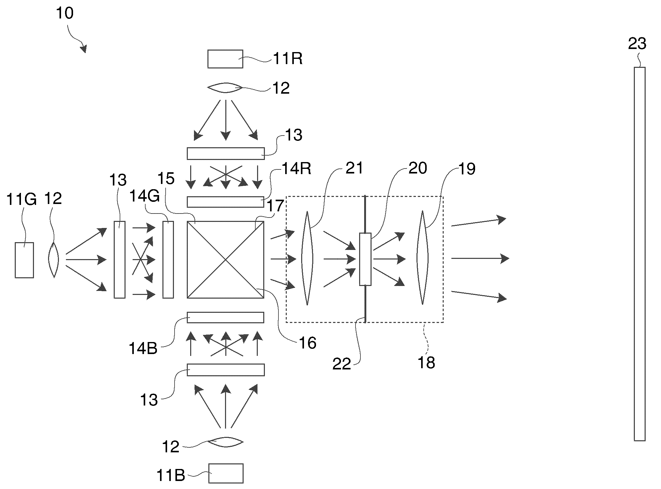
[0010]It is preferably that the projector further includes a projection system that projects the light modulated by the spatial light modulation unit, and the polarized light modulation unit is provided in the projection system. The above configuration allows the polarization state of the light outputted from the spatial light modulation unit to be changed. Further, disposing the polarized light modulation unit in the projection system allows the projector to be smaller than a case where the polarized light modulation unit is disposed outside the projection system.
[0011]It is preferably that the polarized light modulation unit is disposed where an aperture of the projection system is positioned. Positioning the polarized light modulation unit in the aperture in the projection system where the light converges and has the smallest size allows the polarized light modulation unit to be reduced in size. A small polarized light modulation unit also allows the projection system to be smaller than a case where the polarized light modulation unit is not disposed in the aperture but in any other position in the projection system.

Problems solved by technology

A speckle pattern recognized in a displayed image gives a viewer a sense of glaring flicker, disadvantageously affecting the viewed image.
However, a mechanical driving unit, when necessary to rotate or oscillate the diffusion element, may lower the reliability of the apparatus and make the apparatus less quiet.
Further, the diffusion element may be required to be highly durable against the motion of the mechanical driving unit, resulting in increase in cost.
In the technology of the related art, it is disadvantageously difficult to reduce speckle noise without using a mechanical driving unit.

Method used


Image

  • Projector
  • Projector
  • Projector

Examples


first embodiment

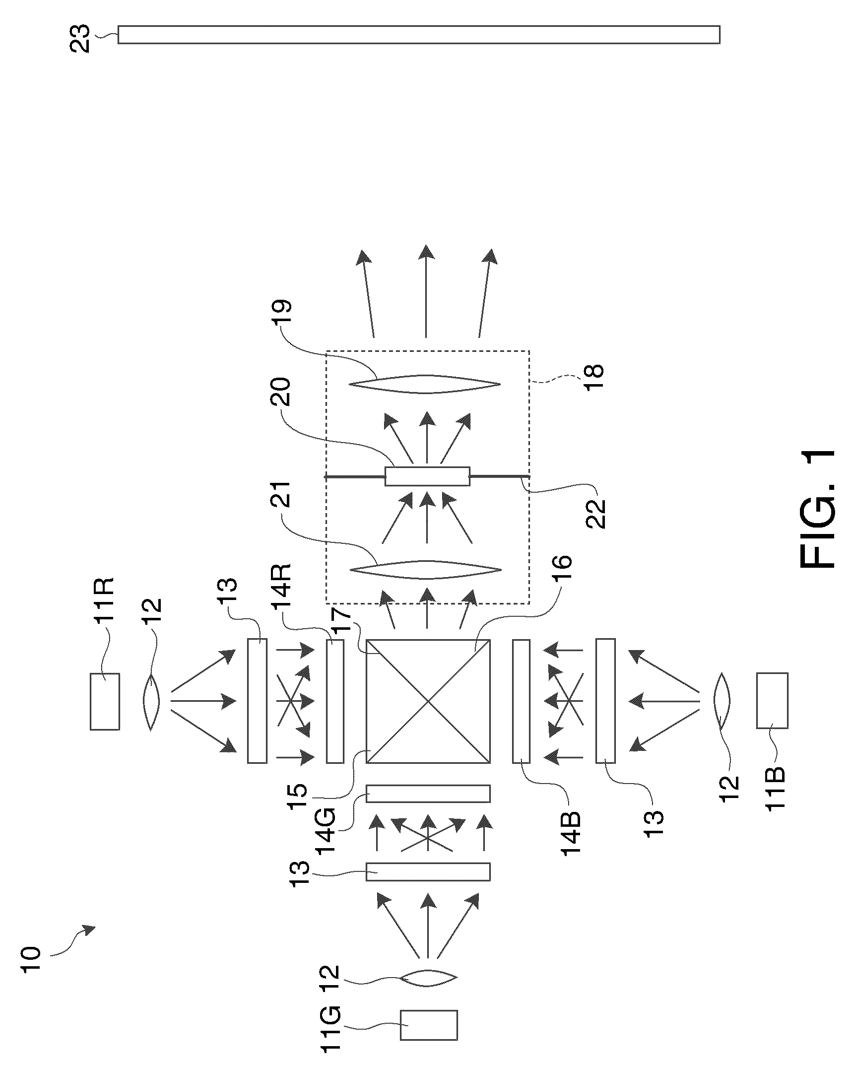
[0020]FIG. 1 diagrammatically shows the configuration of a projector 10 according to a first embodiment of the invention. The projector 10 is a front-projection projector, which projects light on a screen 23 and presents an image to a viewer who observes the light reflected off the screen 23. A light source apparatus for red (R) light 11R, a light source apparatus for green (G) light 11G, and a light source apparatus for blue (B) light 11B serve as light source units that emit laser light, which is coherent light.

[0021]The light source apparatus for R light 11R is a laser light source that emits R laser light and includes a semiconductor laser or any other suitable laser. An enlarging lens 12 enlarges a laser light flux from the light source apparatus for R light 11R. A diffraction optical element 13 diffracts the laser light that has passed through the enlarging lens 12 and outputs the diffracted light. The diffraction optical element 13 shapes and enlarges an illumination area and...

second embodiment

[0043]FIG. 5 diagrammatically shows a characteristic portion of a projector according to a second embodiment of the invention. The present embodiment is characterized in that a liquid crystal device for modulating polarized light 44 is disposed where an intermediate image is positioned. The same portions as those in the first embodiment have the same reference characters and redundant description thereof will be omitted. A focusing system 41 and the liquid crystal device for modulating polarized light 44 are provided within the optical path between the cross dichroic prism 15 and a projection lens 45. The focusing system 41 has a first lens 42 and a second lens 43. The focusing system 41 forms an intermediate image of the image formed by the spatial light modulators for the R, G, B light 14R, 14G, 14B.

[0044]The first lens 42 and the second lens 43 form a telecentric optical system. The principal light ray incident on the first lens 42 becomes substantially parallel to the optical ax...


PUM


Abstract

A projector includes a light source unit that emits coherent light, a spatial light modulation unit that modulates the coherent light emitted from the light source unit in accordance with an image signal, and a polarized light modulation unit having a plurality of modulating areas, each of which changing the polarization state of light. The plurality of modulating areas temporally and spatially change the polarization state of the light outputted from the spatial light modulation unit.

Description

BACKGROUND[0001]1. Technical Field[0002]The present invention relates to a projector, and particularly to a technology of a projector that uses laser light to display an image.[0003]2. Related Art[0004]A technology using a laser light source as the light source of a projector has been proposed in recent years. A laser light source, as compared with a UHP lamp that has been used as the light source of a projector, has various advantages including excellent color reproducibility, quick start, and a long life. Laser light, which is coherent light, applied onto a screen or any other diffusing surface produces in some cases interference fringes called a speckle pattern having bright and dark dots randomly distributed. A speckle pattern is produced when light beams diffused by the diffusing surface randomly interfere. A speckle pattern recognized in a displayed image gives a viewer a sense of glaring flicker, disadvantageously affecting the viewed image. To avoid such a situation, when a ...

Claims


Application Information

Patent Timeline
IPC IPC(8): G02F1/01G03B21/14
CPCG02B13/22G03B21/14G02F2203/12G03B21/2073G03B21/208
Inventor ARUGA, SUSUMU
Owner SEIKO EPSON CORP
Learn More