Radial counterflow shear electrolysis

a technology of counterflow and shear electrolysis, which is applied in the direction of electrolysis components, electrolysis processes, coatings, etc., can solve the problems of not keeping pace with technology, no economical means for carbon capture and sequestration at coal plants, amine scrubbing and underground storage, etc., to avoid the accumulation of high-quality metallic nanotubes, avoid the effect of falling ions and avoiding electrode erosion

Inactive Publication Date: 2009-08-13
VORSANA INC
View PDF99 Cites 23 Cited by
  • Summary
  • Abstract
  • Description
  • Claims
  • Application Information

AI Technical Summary

Benefits of technology

[0039]A radial counterflow forcing regime, comprising the centrifugal impellers and an axial suction pump, creates simultaneous source-sink flow in the workspace: sink flow of light fraction products of electrolysis toward the impeller / electrode axis of rotation, and source flow of feed and heavy fraction products away from the axis. Radial counterflow (von Karman swirling flow in an open system) assures high continuous mass flow through the reactor and long residence time for cracking and centrifugal separation of products. Fine scale vortices in a shear layer between the impeller / electrodes perform centrifugal separation, and larger scale vortices communicating with the fine scale vortices provide radial sink flow conduits for low density light fraction products of electrolysis, such as hydrogen from water or methane.
[0049]By means of the present invention, carbon dioxide, which is presently worse than worthless, becomes a valuable resource. Emitters of carbon dioxide have a way to avoid the problems of sequestration, and a profit motive to prevent global climate change.

Problems solved by technology

It is generally agreed that carbon dioxide emissions must be brought under control, but technology has not kept pace with policy.
There is no economical means for carbon capture and sequestration at coal plants.
Amine scrubbing and underground storage, the leading current proposals for carbon capture and sequestration, would be prohibitively expensive, and there is good reason to doubt that they would be reliable.
The volume of the waste stream is overwhelmingly large.
The air-blown gasifier is inferior to the gasifier which uses pure oxygen.
The enormous volume and weight that must be transported and injected, and the lack of any assurance that the carbon dump will remain secure, should give preference to some sort of treatment at the plant instead of dumping, but presently no carbon dioxide treatment is feasible for the large volumes of hot and dirty waste gas emitted by utilities and industries.
Cement plants and refineries and steel mills are also heavy polluters.
Transporting that much weight and putting that much volume underground every year would be an expensive undertaking.
Buried carbon dioxide gas may percolate back to the surface and leak out to harm people or at least escape into the atmosphere.
Nuclear waste is still without a site for permanent sequestration, and its volume is minuscule compared to the volume of carbon dioxide waste from only one plant.
If the pressure is increased to cram more carbon dioxide into available dump space, the danger of leaks, migrations, and eruptions increases.
When the likelihood of human error, dishonesty, and greed—as well as earthquakes and other natural disasters—are considered as well, there no reason to expect that public approval can be obtained for sitting carbon dumps.
In summary, sequestration is not only prohibitively expensive but also not feasible as a long term solution.
The air separator accounts for approximately 30% of the operation and maintenance cost of the plant.
The cell is not only expensive, but small.
Arc discharges which connect the anode and the cathode are undesirable not only because they result in a short circuit of the energy so it does not get dissipated into the gas, but also they cause electrode erosion.
However, the interposed resistance of the dielectric weakens the E field in the gas between the electrodes, so the electromotive force driving electrical energy into the gas is weak.
Thermal plasma processes, which require high pressures, are impractical for carbon dioxide cracking on an industrial scale.
Low (atmospheric) pressure means that the gas molecules excited by electron collisions cannot bump into each other frequently enough to come to thermal equilibrium.
A disadvantage of known glidarc reactors is that residence time of feed gas in the processing zone between the electrodes is short.

Method used


Image

  • Radial counterflow shear electrolysis
  • Radial counterflow shear electrolysis
  • Radial counterflow shear electrolysis

Examples


Embodiment Construction

[0091]By the term “electrolysis” is meant processes which cause molecular dissociation by electrical energy, including processes where dissociation occurs at electrode surfaces as well as processes where molecular dissociation occurs in the bulk fluid (gas, liquid, or combination thereof) between oppositely charged electrodes, including pulsed electric field processes and capacitively coupled plasma processes.

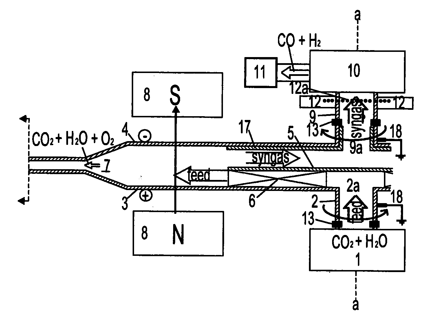
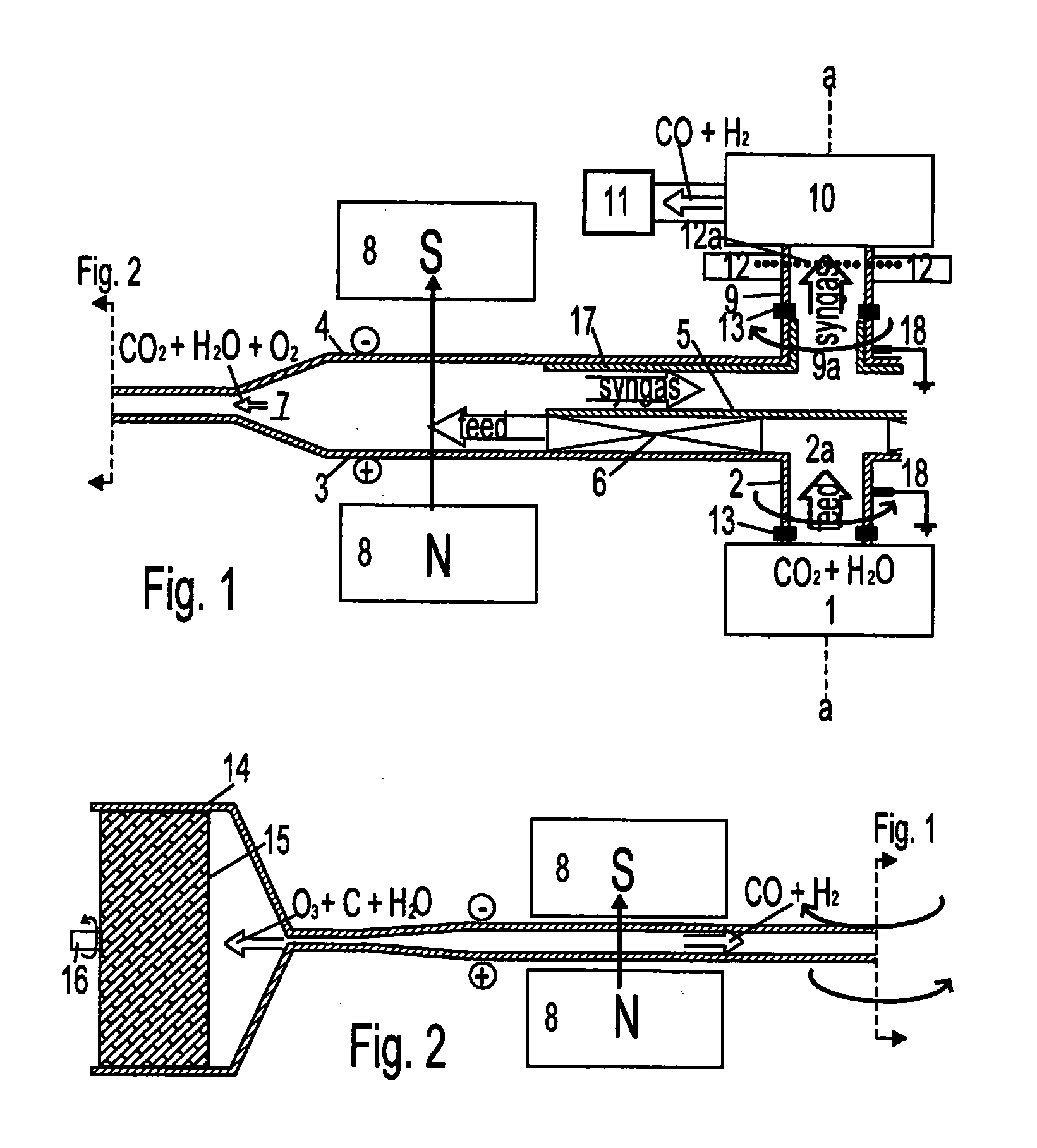
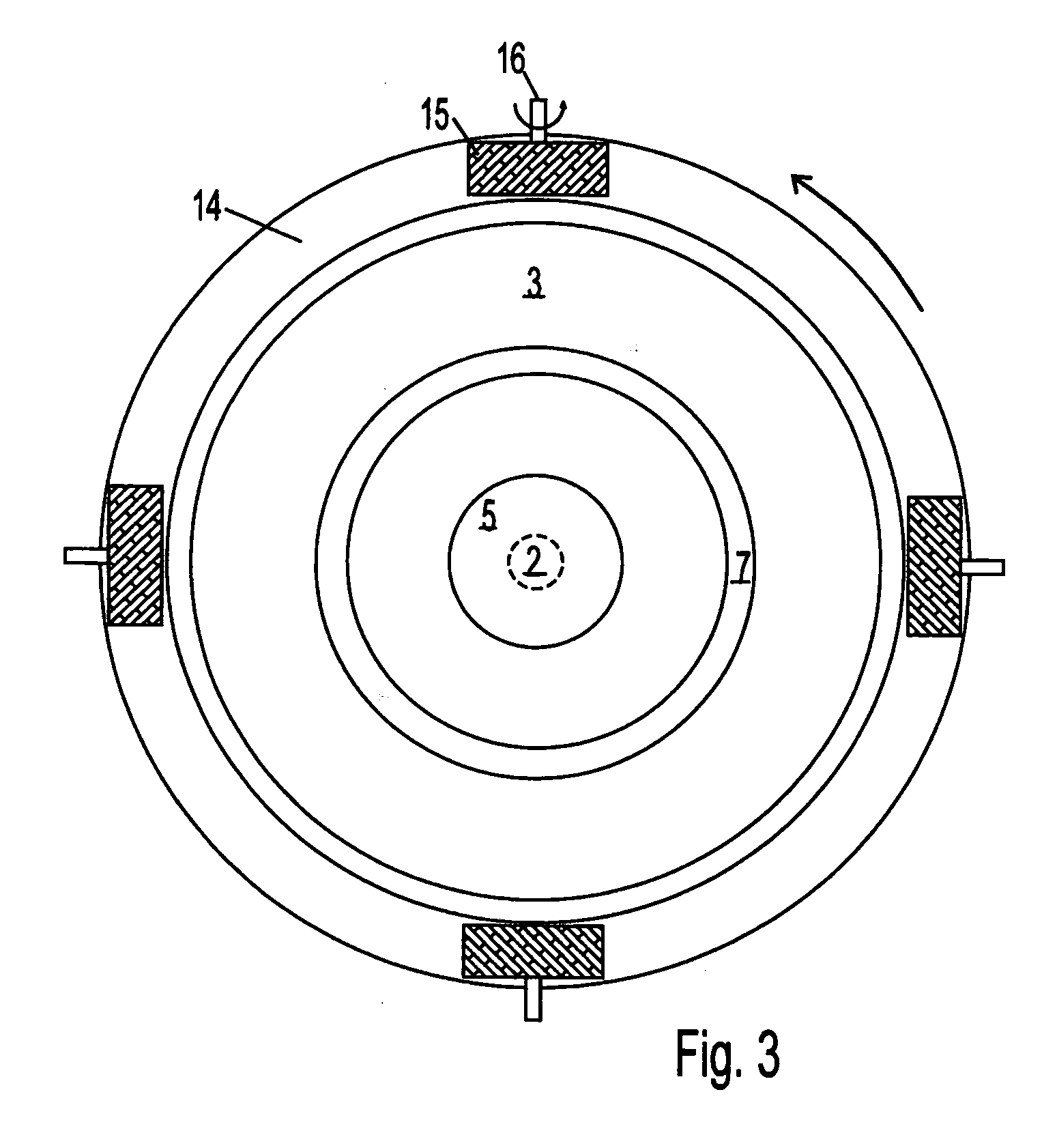
[0092]FIG. 1 and FIG. 2 together show a schematic cross-sectional view of the preferred embodiment for simultaneous electrolysis of carbon dioxide and water to produce syngas. FIG. 1 connects to FIG. 2 to show approximately one half of the reactor according to the present invention. The remainder is symmetrical to what is shown.

[0093]Another application of the present invention according to the preferred embodiment is to crack carbon dioxide or other carbonaceous feed gas including methane and other alkanes, to synthesize carbon nanotubes. The flow paths for the various fractio...


PUM

PropertyMeasurementUnit
Fractionaaaaaaaaaa
Magnetic fieldaaaaaaaaaa
Electrical conductoraaaaaaaaaa

Abstract

Coaxial disk armatures, counter-rotating through an axial magnetic field, act as electrolysis electrodes and high shear centrifugal impellers for an axial feed. The feed can be carbon dioxide, water, methane, or other substances requiring electrolysis. Carbon dioxide and water can be processed into syngas and ozone continuously, enabling carbon and oxygen recycling at power plants. Within the space between the counter-rotating disk electrodes, a shear layer comprising a fractal tree network of radial vortices provides sink flow conduits for light fractions, such as syngas, radially inward while the heavy fractions, such as ozone and elemental carbon flow radially outward in boundary layers against the disks and beyond the disk periphery, where they are recovered as valuable products, such as carbon nanotubes.

Description

APPLICATION HISTORY[0001]This application claims the benefit of U.S. Provisional Patent Applications Nos. 61 / 034,242 filed Mar. 6, 2008 and 61 / 026,963 filed Feb. 7, 2008.FIELD OF THE INVENTION[0002]This invention applies to mechanically-assisted electrolytic dissociation in a continuous process. One particular application of the reactor according to the present invention is simultaneous electrolysis of carbon dioxide and water to produce syngas, a mixture of carbon monoxide and hydrogen, thus providing means for carbon and oxygen recycling at IGCC power plants. Another application is electrolysis of water or methane to produce hydrogen for fuel. Yet another application is cracking of CO2 as an alternative to carbon sequestration. And another application is high volume continuous synthesis of carbon or other nanotubes.BACKGROUND OF THE INVENTIONCarbon Dioxide Emissions.[0003]It is generally agreed that carbon dioxide emissions must be brought under control, but technology has not kep...

Claims


Application Information

Patent Timeline
IPC IPC(8): C25B1/13C25D17/10C25B1/02
CPCC25B1/00C25B1/13C25B9/125C25D17/00C25B1/24Y02E60/368C25D11/024C25B1/02C25D17/10Y02E60/36C25B9/30C25B11/034
Inventor MCCUTCHEN, WILMOT H.MCCUTCHEN, DAVID J.
Owner VORSANA INC
Why Eureka
Try Eureka