
Battery pack

a battery pack and multi-cell technology, applied in the field of multi-cell battery packs, can solve the problems that the batteries used in these applications may generate significant heat during operation, and achieve the effects of improving performance, efficient thermal management, and optimal flow through the battery pack

Active Publication Date: 2009-07-30
COBASYS LLC
View PDF3 Cites 54 Cited by
  • Summary
  • Abstract
  • Description
  • Claims
  • Application Information

AI Technical Summary

Benefits of technology

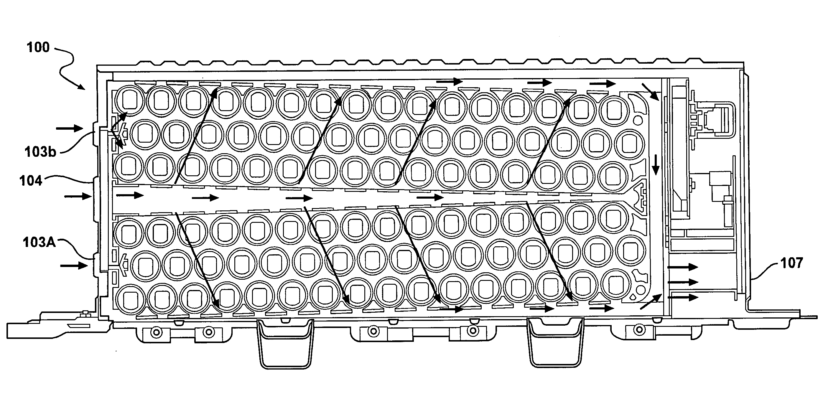
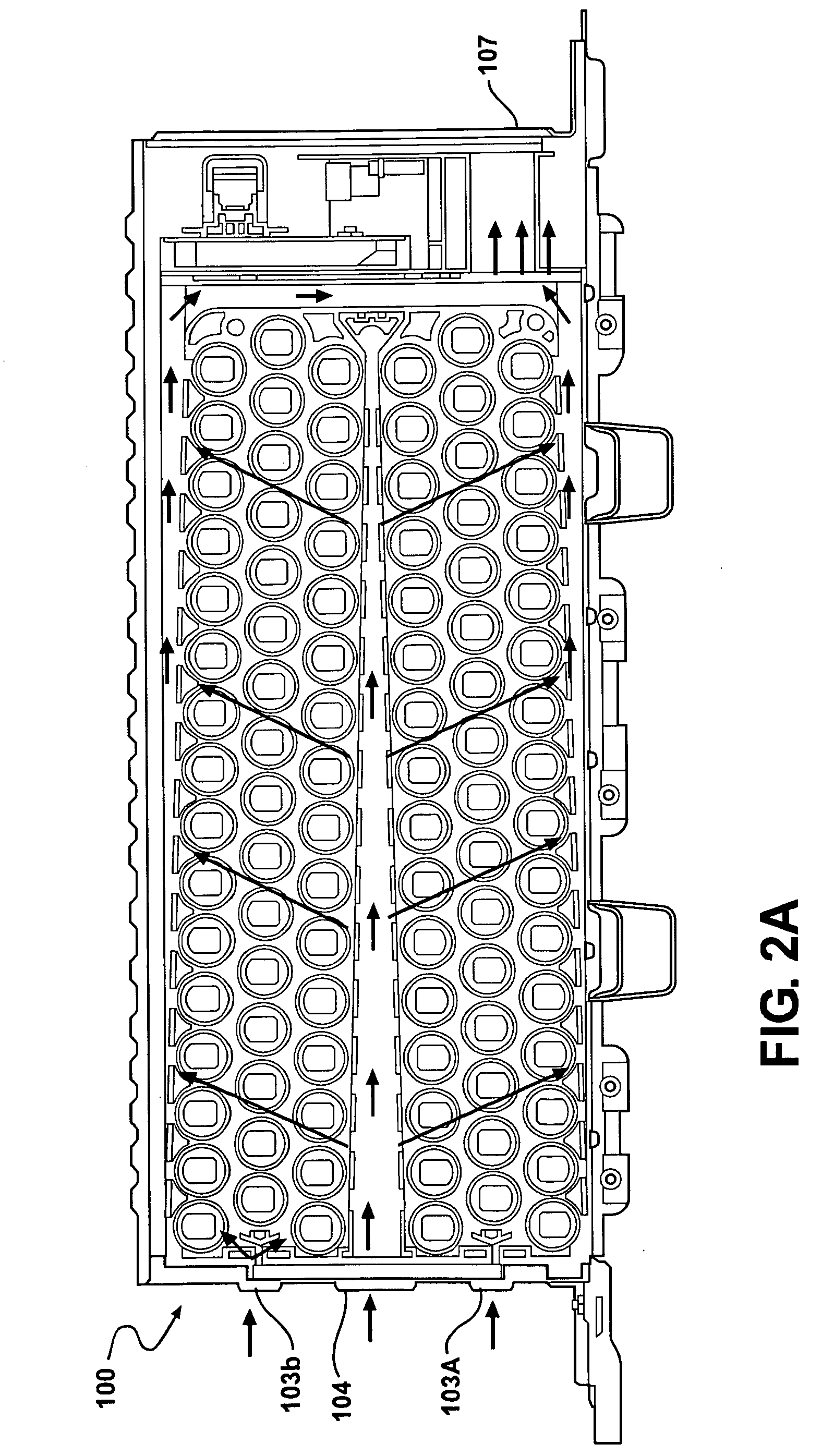
[0008]Disclosed herein is a battery pack which provides optimal temperature distribution throughout the battery pack, wherein maximum cell temperature (Tmax) and temperature differential amongst all cells in the battery pack (ΔTcell) are optimized for efficient thermal management providing safety, improved performance and extended life of the battery pack and electrochemical cells. Preferably, ΔTcell is less than 5° C. Also disclosed herein is a battery pack which provides optimal flow through the battery pack and minimal pressure drop (ΔP) throughout the battery pack.
[0009]An objective of a preferred embodiment of the present invention is to provide a battery pack having a uniform temperature distribution amongst the cells with minimum peak temperatures, and minimal pressure drop associated with the air flow. Minimizing the peak temperature of the cells is also important because it increases the life of the cells. Maintaining uniform temperature across the battery is important to maintain the pack performance and longevity.
[0015]Disclosed herein is a battery pack having a uniform temperature distribution on the cells with minimum peak temperatures, and low pressure drop associated with the air flow within the battery pack. Disclosed herein is a battery pack having efficient heat transfer and high temperature cut. Disclosed herein is a battery pack having minimal peak temperature of the cells and uniform temperature across the battery pack to increase the pack performance and maintain longevity.

Problems solved by technology

Therefore, the batteries used in these applications may generate significant heat during operation.

Method used


Image

  • Battery pack
  • Battery pack
  • Battery pack

Examples


Embodiment Construction

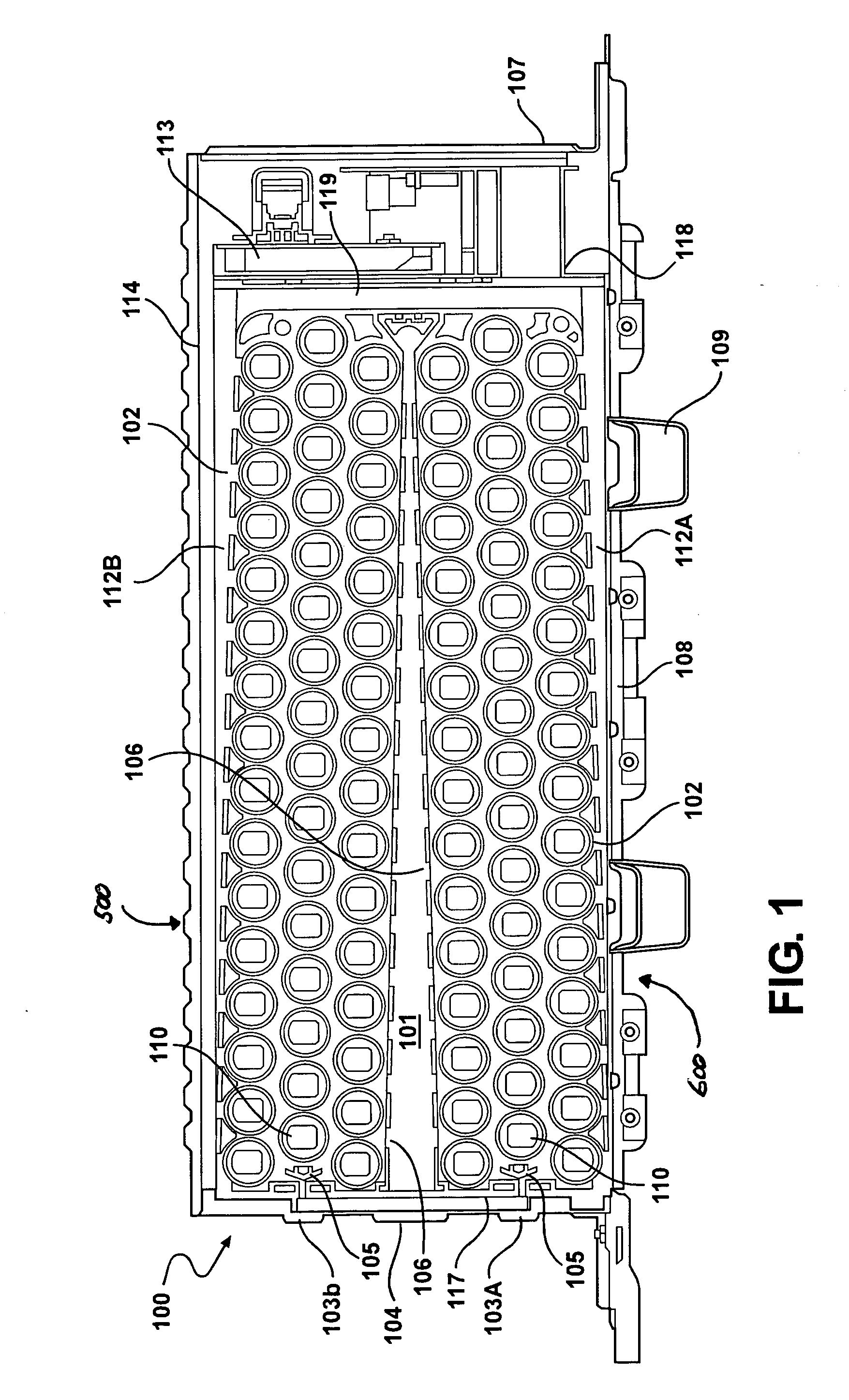
[0034]The battery pack, generally referred to as 100, described herein provides a housing 111 having a front 117, a rear 118, a base 108 and a lid 114, as illustrated in FIG. 1. A first battery assembly, generally referred to as 500, is arranged within the housing 111 upon a first axis forming an angle acute to the base 108 forming a diverging air flow path 112A between the first battery assembly 500 and the base 108. A second battery assembly, generally referred to as 600, is arranged within the housing111 upon a second axis forming an angle acute to the lid 114 forming a diverging air flow path 112B between the first battery assembly 600 and the lid 114 and forming a converging path 101, referred to as the primary cooling cavity, between the first and second battery assemblies 500 and 600. Preferably, the electrochemical cells 110 are cylindrical cells positioned perpendicular to the front 117 to rear 118 axis of the battery pack 100. The cell assemblies are preferably arranged in...


PUM

PropertyMeasurementUnit
electrical currentaaaaaaaaaa
angleaaaaaaaaaa
temperatureaaaaaaaaaa

Abstract

Disclosed herein is a multi-cell battery pack having optimal temperature distribution throughout the battery pack and optimal air flow through the battery pack. Disclosed herein is a battery pack which provides optimal temperature distribution throughout the battery pack, wherein maximum cell temperature (Tmax) and temperature differential amongst all cells in the battery pack (ΔTcell) are optimized for efficient thermal management providing safety, improved performance and extended life of the battery pack and electrochemical cells. Also disclosed herein is a battery pack which provides optimal flow through the battery pack and minimal pressure drop (ΔP) throughout the battery pack.

Description

CROSS-REFERENCING TO RELATED APPLICATIONS[0001]This application claims the benefit of U.S. Provisional Application No. 61 / 062,779, filed on Jan. 29, 2008, which is hereby incorporated herein by reference in its entirety.FIELD OF THE INVENTION[0002]The instant invention relates generally to improvements in rechargeable high performance batteries, modules and packs. Specifically, the invention relates to multi-cell battery pack having optimal temperature distribution throughout the battery pack and optimal air flow through the battery pack.BACKGROUND[0003]Rechargeable batteries are used in a variety of industrial and commercial applications such as fork lifts, golf carts, uninterruptible power supplies, pure electric vehicles and hybrid electric vehicles. Vehicular applications include applications related to propulsion as well as applications related to starting, lighting and ignition.[0004]One aspect of battery operation that is particularly important for electric vehicle and hybrid...

Claims


Application Information

Patent Timeline
Patent Type & Authority Applications(United States)
IPC IPC(8): H01M10/50H01M6/42
CPCH01M6/42H01M10/04H01M10/5004H01M10/5073H01M10/5016H01M10/503H01M10/5067H01M10/5008H01M10/613H01M10/617H01M10/625H01M10/643H01M10/6563H01M10/6566Y02E60/10
Inventor ANANTHARAMAN, SATISHGNANAPRAKASAM, PRADEEPKUMAR, RAGHAV SAMPATHCHANEY, RAYMOND E.GOROG, JOZEFKARDITSAS, NICK
Owner COBASYS LLC
Learn More