High-voltage differential amplifier and method using low voltage amplifier and dynamic voltage selection

Active Publication Date: 2009-07-09
TEXAS INSTR INC
View PDF2 Cites 68 Cited by
  • Summary
  • Abstract
  • Description
  • Claims
  • Application Information

AI Technical Summary

Benefits of technology

[0016]It is another object of the invention to provide a current shunt amplifier having a common mode input voltage range which extends substantially beyond the power supply voltage and which also provides high accuracy current measurement without trimming of circuit components such as resistors.
[0021]In a described embodiment, the output (73) of the comparator (70) is coupled to a control terminal of the first switch (S1) and to an input of an inverter (74) having an output (76) coupled to a control terminal of the second switch (S2). A first level shifter (77) is coupled between the output (76) of the inverter (74) and a control terminal (78) of the second switch (S2). In a described embodiment, the first supply voltage (VREG) is an output of a voltage regulator (71) which receives a second supply voltage (VDD) as an input. The comparator (70) has a sufficient amount of hysteresis to avoid excessive switching of the first (S1) and second (S2) switches. A second level shifter (80,81) has a first terminal coupled to receive the first internal rail voltage (VRAIL-TOP) and a second terminal coupled to a terminal (83) of current source (81) to produce a second internal rail voltage (VRAIL-BOTTOM) on that terminal (83).

Problems solved by technology

These requirements necessitate an undesirably large die size for implementation of current shunt amplifier 1A.
Another drawback of current shunt amplifier 1A is that its circuitry does not function well when the differential input voltage across shunt resistor 5 is near 0 volts.
Unfortunately, current shunt amplifier 1B of Prior Art FIG. 2 has the drawbacks of high noise and large die size.
The topology of instrumentation amplifier IC has two major problems, the first being that the CMRR (common mode rejection ratio) is heavily dependent on the matching of the various resistor ratios.
The second problem is that the common mode input range (CMIR) is limited by VDD, as is also the case for the shunt amplifiers of FIGS. 1 and 2.

Method used


Image

  • High-voltage differential amplifier and method using low voltage amplifier and dynamic voltage selection
  • High-voltage differential amplifier and method using low voltage amplifier and dynamic voltage selection
  • High-voltage differential amplifier and method using low voltage amplifier and dynamic voltage selection

Examples


Embodiment Construction

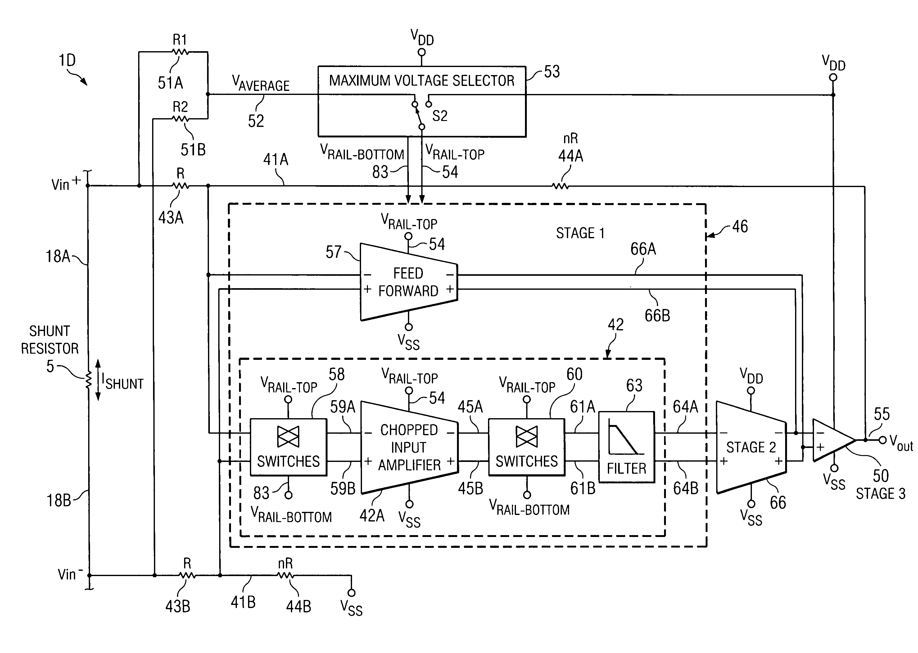
[0035]The present invention extends the common mode input range of a current shunt amplifier beyond the power supply voltage by utilizing the common mode input voltage to power the input stage, allowing electrical “floating” of a low voltage amplifier in the input stage.

[0036]Referring to FIG. 4, current shunt amplifier 1D measures the voltage Vin+−Vin− produced between the terminals 18B and 18A of external shunt resistor 5 in response to a shunt current ISHUNT, and includes a first or “front end” stage input pre-amplifier 46, a conventional second stage amplifier 66, and a conventional third or output stage amplifier 50. First stage input pre-amplifier 46 includes a chopper-stabilized input amplifier 42 which includes input amplifier 42A and its associated input chopping switches 58, its associated output chopping switches 60, and a digital filter 63. Input amplifier 42A has its (−) and (+) inputs coupled by means of conductors 59A and 59B, respectively, to outputs of chopping swit...


PUM


Abstract

A differential amplifier (1D) includes circuitry (5,R1,R2,52) coupling a common mode component of an input voltage (Vin+−Vin−) to a maximum voltage selector circuit (53) that produces an internal voltage (VRAIL-TOP) equal to the larger of a first supply voltage (VREG) and the common mode component. An input amplifier circuit (46) of the differential amplifier is powered by the internal voltage. The input voltage (Vin+−Vin−) is coupled to inputs (41A,B) of the input amplifier circuit (46). Outputs (64A,B) of the input amplifier circuit (46) are amplified by an output amplifier (50).

Description

CROSS REFERENCE TO RELATED APPLICATION[0001]This application claims the benefit of prior filed co-pending U.S. provisional application Ser. No. 61 / 019,023 filed Jan. 4, 2007, entitled “High-Voltage Differential Amplifier Topology Using Low Voltage Amplifier and Dynamic Voltage Selection”, by Shoubao Yan, Gerald W. Steele, and David R. Baum, and incorporated herein by reference.BACKGROUND OF THE INVENTION[0002]The present invention relates generally to current shunt amplifiers, and more particularly to improving the common mode input range thereof well beyond the power supply voltage.[0003]Referring to Prior Art FIG. 1, the illustrated current shunt amplifier 1A measures the voltage produced across an external shunt resistor 5. Current shunt amplifier 1A includes an operational amplifier 2 having its (−) input connected by a conductor 8 to one terminal of an input resistor 3 and to the drain of a N-channel output transistor 7. The other terminal of input resistor 3 is connected by co...

Claims


Application Information

Patent Timeline
IPC IPC(8): H03F3/45
CPCH03F1/0216H03F3/387H03F3/393H03F2200/513H03F3/45475H03F3/45632H03F3/45928H03F3/45219
Inventor YAN, SHOUBAOSTEELE, GERALD W.BAUM, DAVID R.
Owner TEXAS INSTR INC
Why Eureka
Try Eureka