
Digitally compensated highly stable holdover clock generation techniques using adaptive filtering

a technology of adaptive filtering and holdover clock, which is applied in the direction of oscillator generators, generator stabilization, pulse automatic control, etc., can solve the problems of high cost, high output frequency drift, and inability to meet strict stability requirements

Active Publication Date: 2009-07-02
INTEGRATED DEVICE TECH INC
View PDF4 Cites 33 Cited by
  • Summary
  • Abstract
  • Description
  • Claims
  • Application Information

AI Technical Summary

Benefits of technology

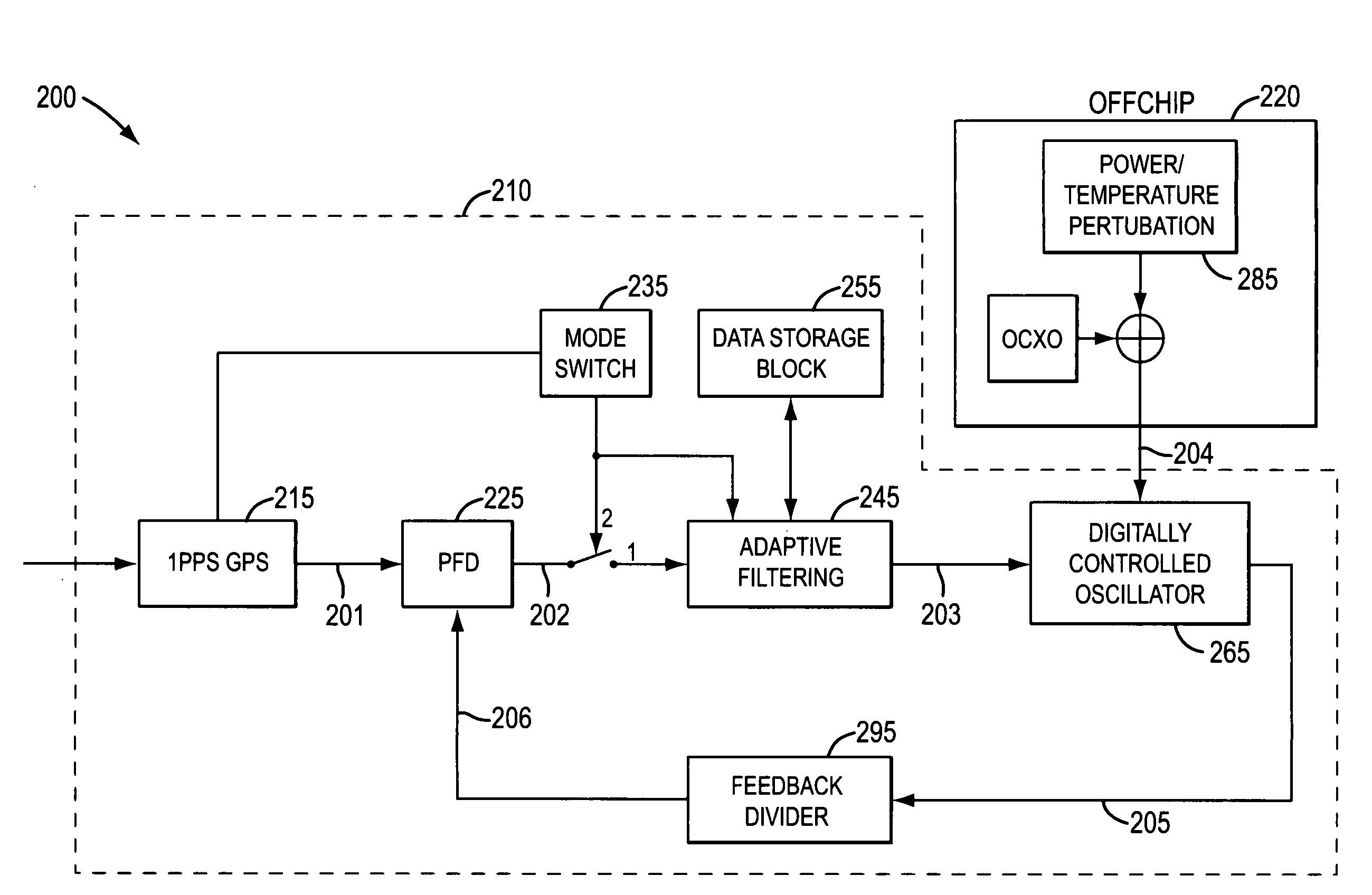
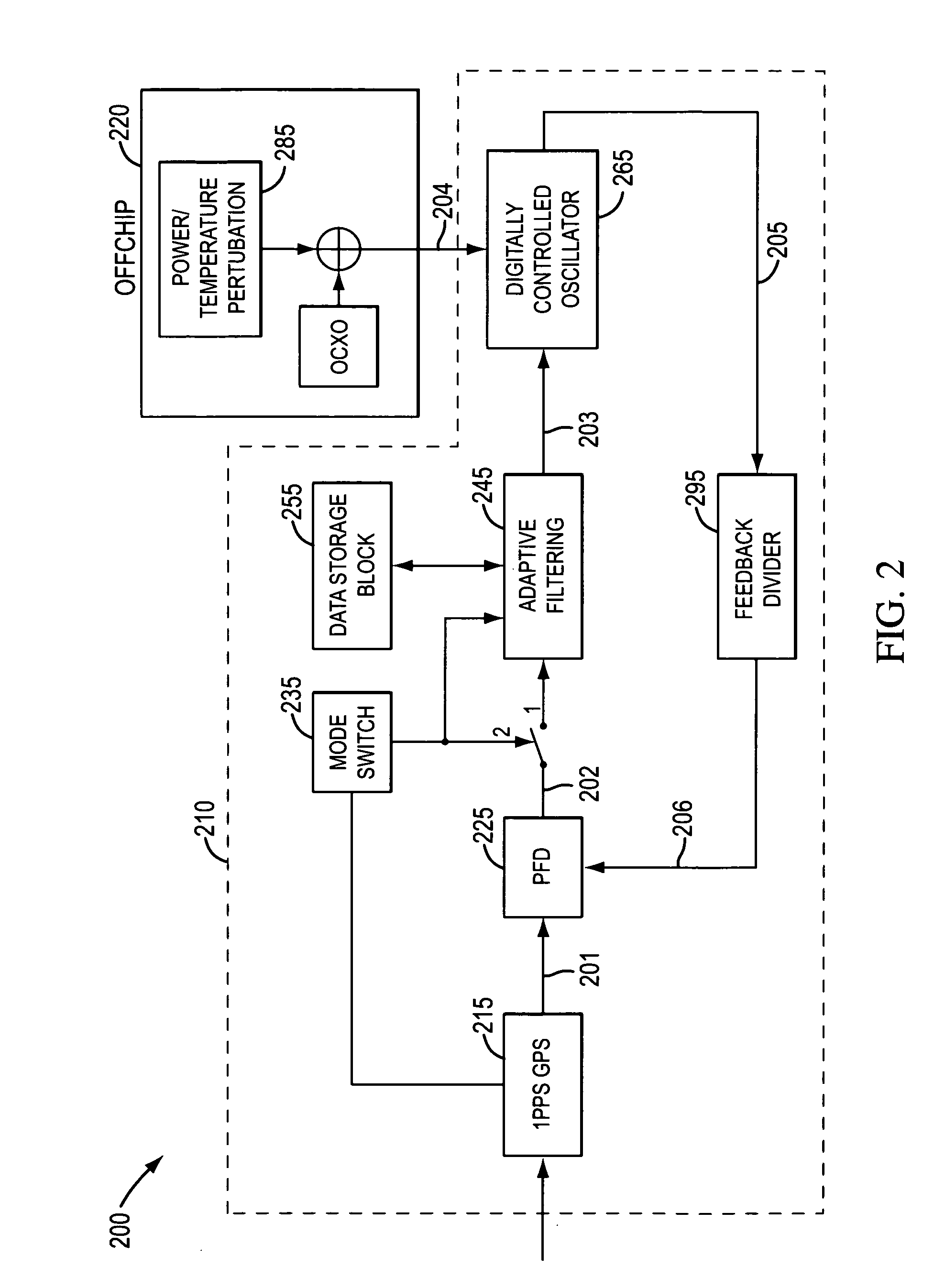
The present invention provides a system and method for generating a stable output clock signal. The system includes an oven controlled crystal oscillator, a receiver, and a phase and frequency detector. The system also includes a data storage block that stores model parameters to predict frequency variations of the clock signal, an adaptive filtering module that predicts frequency variations of the clock signal based on the model parameters, and an output selector to generate a data signal. The system can operate either in normal mode or holdover mode. The method involves generating an input reference clock signal, updating the model parameters, and generating an output clock signal based on the input reference clock signal and the model parameters. The system and method provide a highly stable output clock signal even in situations where the input reference clock signal is unavailable.

Problems solved by technology

A RbXO can generally meet the strict stability requirements easily, but is very expensive.
With carefully designed peripheral circuits, it is possible for OCXOs to meet the stability requirements, but at the cost of increased system complexity.
All solutions of holdover clocks based on OCXOs suffer from aging effects of the crystals, which causes the output frequency to drift.
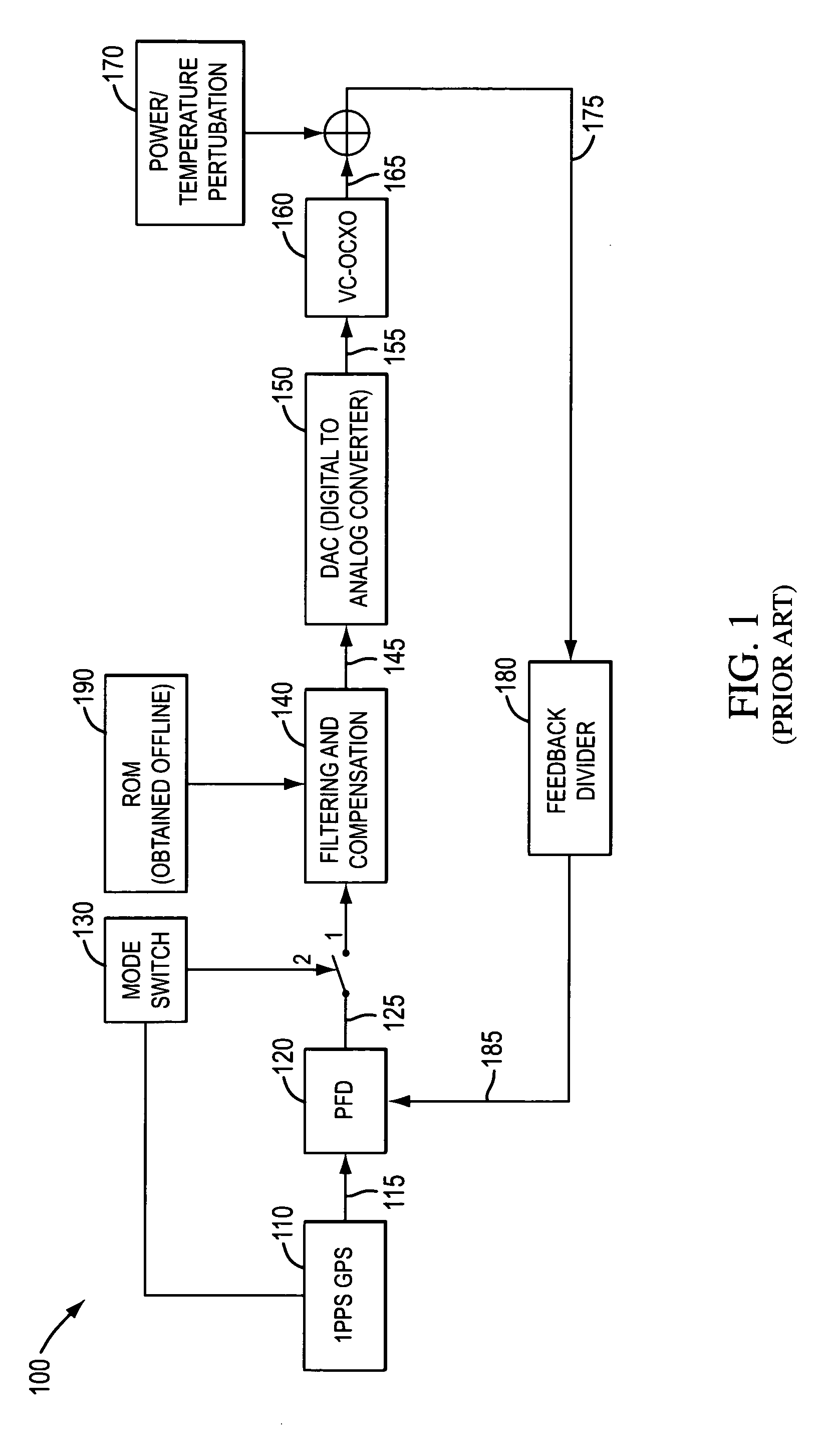
One major disadvantage of this approach is that the voltage signal used to control the output clock signal of a VC-OCXO is prone to circuit noise; therefore, accuracy or stability of the output clock signal is often degraded.

Method used


Image

  • Digitally compensated highly stable holdover clock generation techniques using adaptive filtering
  • Digitally compensated highly stable holdover clock generation techniques using adaptive filtering
  • Digitally compensated highly stable holdover clock generation techniques using adaptive filtering

Examples


Embodiment Construction

[0019]FIG. 1 shows a schematic diagram illustrating a discrete circuit for generating a holdover clock using a VC-OCXO. Circuit 100 includes a Global Positioning System (“GPS”) receiver 110, a Phase and Frequency Detector (“PFD”) 120, a switch 130, a Filtering and Compensation module (“FC”) 140 coupled to a Read Only Memory (“ROM”) 190, a Digital to Analog Converter (“DAC”) 150, a VC-OCXO 160 with Power / Temperature Perturbation 170, and a Feedback Divider (“FD”) 180. GPS receiver 110 receives and generates input reference clock signal 115 from GPS receiver 110. PFD 120 receives input reference clock signal 115 and feedback clock signal 185 and generates error signal 125 representing the phase difference between input reference clock signal 115 and feedback clock signal 185. When switch 130 is in position “1”, error signal 125 is connected to FC 140. FC 140 then filters error signal 125 according to filtering parameters stored in ROM 190. Typically, FC 140 filters out jitter in the i...


PUM


Abstract

A system and method for generating a highly stable holdover clock utilizing an integrated circuit and an external OCXO is presented. The integrated circuit comprises an input reference clock receiver, a phase and frequency detector that generates an error signal between the input reference clock signal and a feedback clock signal, a data storage block that stores model parameters to predict frequency variations of the OCXO, an adaptive filtering module that includes a digital loop filter and algorithms for updating the model parameters and predicting frequency variations based on the model, a switch that enables the system to operate in normal or holdover mode, a digitally controlled oscillator, and a feedback divider.

Description

BACKGROUND[0001]1. Field of the Invention[0002]The present invention relates to a clock generation circuit in a communication network and, more specifically, to the systems and methods for generating a digitally compensated highly stable holdover clock.[0003]2. Discussion of Related Art[0004]Many communication networks and devices operate using a reference clock backed by a holdover clock. Network clocks are generally traceable to the reference clock. If the reference clock is unavailable, the network clocks should be traceable to the holdover clock. Certain communication networks require highly stable reference and holdover clocks. For example, the current 2G and the future 3G wireless networks have specific stability requirements for the reference clock, ranging from 0.01 ppm to 0.1 ppb. When the reference clock is lost, the stability of the holdover clock becomes crucial to ensuring reliable connections in the network.[0005]Currently, a holdover clock is generally implemented usi...

Claims


Application Information

Patent Timeline
Patent Type & Authority Applications(United States)
IPC IPC(8): H03L7/099H03L7/00H03L7/085
CPCH03L1/02H03L7/093H03L7/235H03L7/0996H03L7/099
Inventor LIU, XINZHANG, LIANGWANG, YONG
Owner INTEGRATED DEVICE TECH INC
Learn More