
Method of producing a copper alloy wire rod and copper alloy wire rod

a technology of copper alloy wire and wire rod, which is applied in the direction of manufacturing tools, furnaces, heat treatment equipment, etc., can solve the problems of significant obstructed productivity, cracking of ingots upon solidification, and lowering production costs. , to achieve the effect of improving processability, lowering production costs, and excellent properties

Inactive Publication Date: 2009-07-02
FURUKAWA ELECTRIC CO LTD
View PDF1 Cites 15 Cited by
  • Summary
  • Abstract
  • Description
  • Claims
  • Application Information

AI Technical Summary

Benefits of technology

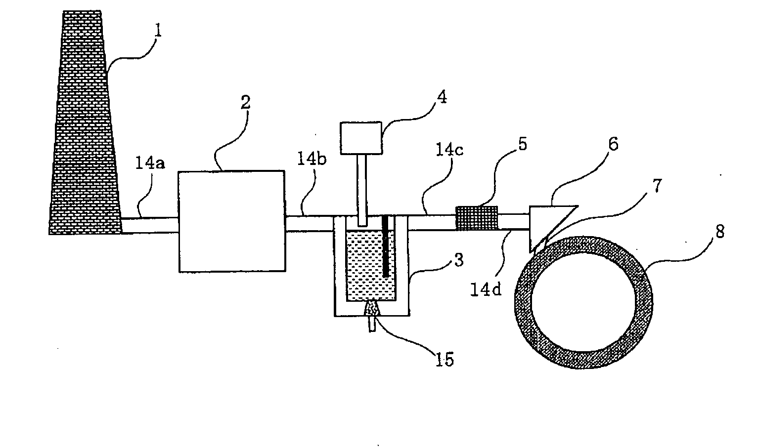
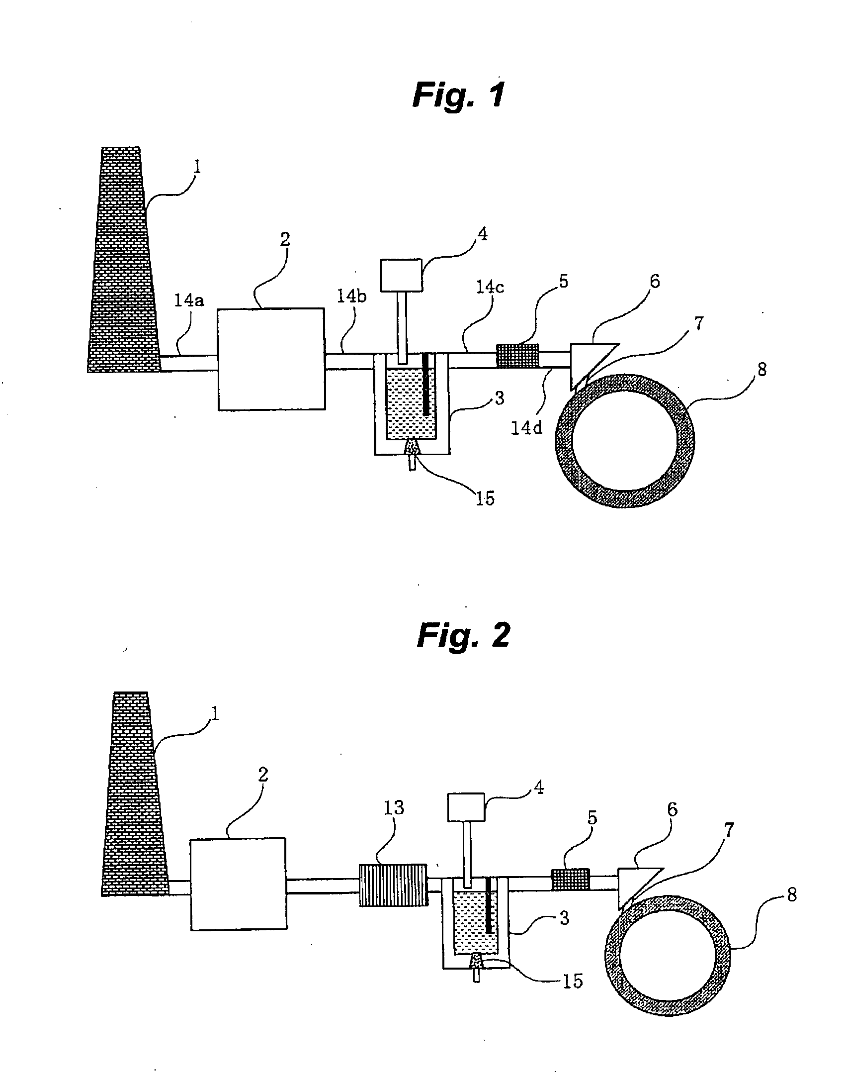
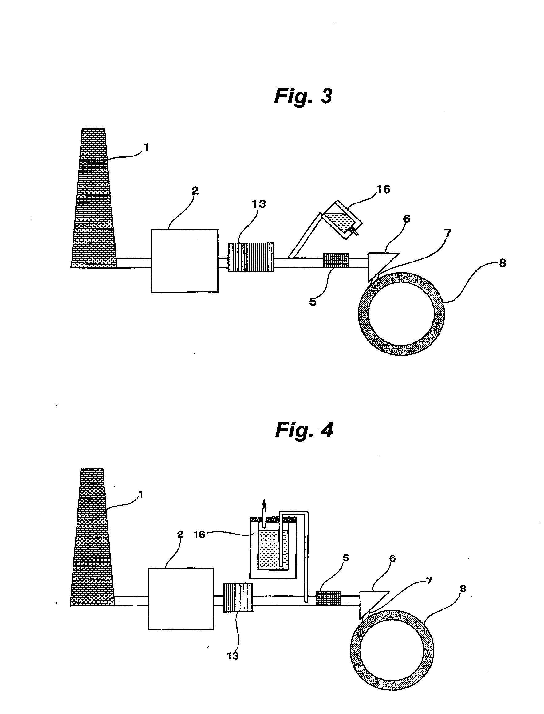
The present invention provides a method for producing a copper alloy wire rod with improved processability and reduced production costs. The method involves a continuous casting and rolling step, where an ingot is obtained by casting molten copper of a precipitation strengthening copper alloy into a movable mold and the ingot is then rolled to form a wire rod. The wire rod is then cooled and quenched. The resulting wire rod has a high solidified shell and excellent properties, such as high strength and ductility. The method can also increase the production speed and reduce the equipment costs by using a movable mold and a continuous casting and rolling step. The invention also provides various copper alloy compositions that can be used for the method.

Problems solved by technology

However, this could not lead to a remarkable lowering of the production costs.
In addition, it has been appeared that methods of producing the copper alloy wire rod using the precipitation strengthening copper alloy other than Corson-based alloy have associated with the similar problems as described in the above.
It is well known that, when producing a large cross section ingot using molten metal, considerable shrinkage in volume occurs due to a phase transformation from a liquid phase to a solid phase (solidification), resulting in occurrence of crack in the ingot upon solidification.
However, when the section of the ingot is downsized, the productivity is significantly obstructed.
An increase of the casting velocity may be applied as a method for improving the productivity, but an air gap is actually occurred to make the primarily cooling insufficient, and thus there is a limit to increase the casting velocity.
Further, in the worst case, sometimes a crucial trouble such as a breakout may occur.

Method used


Image

  • Method of producing a copper alloy wire rod and copper alloy wire rod
  • Method of producing a copper alloy wire rod and copper alloy wire rod
  • Method of producing a copper alloy wire rod and copper alloy wire rod

Examples


example 1

[0098]Copper alloy wire rods having listed wire diameters were produced, by using copper alloys having an alloy composition as shown in Table 1 and using a variety of continuous casting and rolling apparatuses as shown in Table 1. The copper alloy wire rods produced by the method of the present invention are shown in Nos. 1 to 16. Some of the wire rods having the same compositions (Nos. corresponding to are shown in ( )) as those of Nos. 1 to 16 but obtained at different quenching temperature, are shown in Nos. 17 to 23 as comparative examples.

[0099]The electric conductivity of the solution-treated state was measured by measuring electric conductivity of one, which is obtained by quickly cooling in water after maintaining at a temperature of {(solidus temperature)−10° C.} for 1 hour, through a four-prove method. The electric conductivity of the copper alloy wire rod was measured by measuring the electric conductivity of each of the obtained copper alloy wire rods through the four-pr...

example 2

[0103]Hereinbelow, other examples are described in the same way as Example 1. Copper alloy wire rods having listed wire diameters were produced, by using copper alloys having an alloy composition as shown in Table 2 and using a variety of continuous casting and rolling apparatuses as shown in Table 2. The copper alloy wire rods produced by the method of the present invention are shown in Nos. 24 to 35. Further, the wire rods having the same compositions as those of Nos. 24, 29, and 30 but obtained at different quenching temperature, are shown in Nos. 36 to 38, respectively, as comparative examples.

[0104]Herein, the solution-treated rate, casting machine, rolling mill are listed in Table 2 in the same manner as in Example 1.

TABLE 2Solution-CastingDiameterQuenchingtreatedrateRollingof wire rodtemperaturerateNo.Alloy compositionCastor(ton / hr)mill(mm)(° C.)(%)24Cu—0.8Ni—0.4Co—0.3SiSCR52-way66208525Cu—1.8Ni—0.5Co—0.6SiSCR52-way66408726Cu—3.4Ni—1.4Co—1.3SiContirod202-way87909427Cu—1.5Co—0...

example 3

[0107]In the same manner as in Example 1, copper alloy wire rods having listed wire diameters were produced, by using copper alloys having an alloy composition as shown in Table 3 and using the continuous casting and rolling apparatus as shown in Table 3. The copper alloy wire rods produced by the method of the present invention are shown in Nos. 39 to 48. Further, the wire rods having the same compositions as those of Nos. 39, 42, and 43 but obtained at different quenching temperature, are shown in Nos. 49 to 51, respectively, as comparative examples.

[0108]Herein, the solution-treated rate, casting machine, rolling mill are listed in the table in the same manner as in Example 1.

TABLE 3Solution-CastingDiameterQuenchingtreatedrateRollingof wire rodtemperaturerateNo.Alloy compositionCastor(ton / hr)mill(mm)(° C.)(%)39Cu—0.6Ni—0.5SnSCR52-way67409140Cu—1.4Ni—0.7SnSCR52-way67609241Cu—4.5Ni—2.3SnSCR52-way66508842Cu—8.3Ni—2.2Sn—0.12Mg—0.24MnSCR52-way66208743Cu—9.1Ni—3.4Sn—1.0ZnSCR52-way67209...


PUM

PropertyMeasurementUnit
temperatureaaaaaaaaaa

Abstract

A method of producing a copper alloy wire rod, containing: a casting step for obtaining an ingot by pouring molten copper of a precipitation strengthening copper alloy into a belt-&-wheel-type or twin-belt-type movable mold; and a rolling step for rolling the ingot obtained by the casting step, which steps are continuously performed, wherein an intermediate material of the copper alloy wire rod in the mid course of the rolling step or immediately after the rolling step is quenched.

Description

TECHNICAL FIELD[0001]The present invention relates to a method of producing a precipitation strengthening copper alloy wire rod and to a copper alloy wire rod produced by the producing method.BACKGROUND ART[0002]As electronic equipments are getting smaller, thinning of a copper conductor has been required and oxygen-free copper excellent in ductility and processability has been increasingly used. Thus, a method of producing oxygen-free or low-oxygen copper wire rods through a belt & wheel type continuous casting and rolling high in production capacity has been proposed.[0003]Meanwhile, it is known that a precipitation strengthening copper alloy, e.g., a Corson alloy, is remarkably brittle at an intermediate temperature. Therefore, it has been pointed out that there is a need to avoid cracks upon casting. In addition, the heating conditions before hot-rolling have to be also considered sufficiently.[0004]Further, when the copper alloy containing a trace amount of Si or Mg is cast thr...

Claims


Application Information

Patent Timeline
Patent Type & Authority Applications(United States)
IPC IPC(8): C22F1/08C22C9/06C22C9/04C22C9/02C22C9/00
CPCB22D11/004B22D11/0602B22D11/0605C22C9/04C22C9/06C22F1/08C22C9/00B22D11/1206B22D11/12B21B3/00
Inventor YOSHIDA, HIROKAZUTAKAZAWA, TSUKASA
Owner FURUKAWA ELECTRIC CO LTD
Learn More