
Extrusion Die and Process for Producing an Extruded Filled Polymer Composition

Inactive Publication Date: 2009-06-11
MALONE BRUCE A +1
View PDF11 Cites 24 Cited by
  • Summary
  • Abstract
  • Description
  • Claims
  • Application Information

AI Technical Summary

Benefits of technology

[0012]The present invention advances the art by providing an extrusion die and a process using the die that is suitable for efficiently manufacturing filled polymer compositions comprising highly dispersed and uniformly distributed wood filler in a polymer matrix directly from an extruder.

Problems solved by technology

Dispersing filler into a polymer matrix, particularly when the filler and polymer are not especially compatible, has historically been challenging.
The challenge increases as the amount of filler relative to matrix material increases and as product requirements dictate a highly uniform composition.
Manufacturing an extruded composition comprising a hydrophilic filler dispersed in a hydrophobic polymer suffers from such a challenge since the filler and polymer are not especially compatible.
The challenge is more difficult when the filler and / or matrix material has a tendency to thermally degrade, such as is the case for cellulose fillers.
U.S. Pat. No. 4,708,623 ('623) teaches that conventional monoaxial and biaxial extruder screw designs are insufficient for dispersing wood filler into a polymer matrix and discloses a non-conventional screw zone for the purpose of disentangling wood fibers within an extruder.
Additionally, the process of extruding a filled polymer composition into pellets and then subsequently molding the composition pellets into an article is undesirably less efficient than a one-step process that compounds and extrudes a composition into an article in a single step.
As a result, the products of '472 suffer from a non-homogeneous end-on appearance when planed.
Unfortunately, a die producing a compression ratio of at least 3:1 can become inconveniently large when designed to manufacture products having large cross sectional areas.
In addition, or as an alternative, enhancing mixing by increasing a die's compression ratio requires cooling a polymer composition to obtain elevated melt viscosity within the die, which tends to inhibit achieving quality surface appearance of a final extruded product.

Method used


Image

  • Extrusion Die and Process for Producing an Extruded Filled Polymer Composition
  • Extrusion Die and Process for Producing an Extruded Filled Polymer Composition
  • Extrusion Die and Process for Producing an Extruded Filled Polymer Composition

Examples


example 1

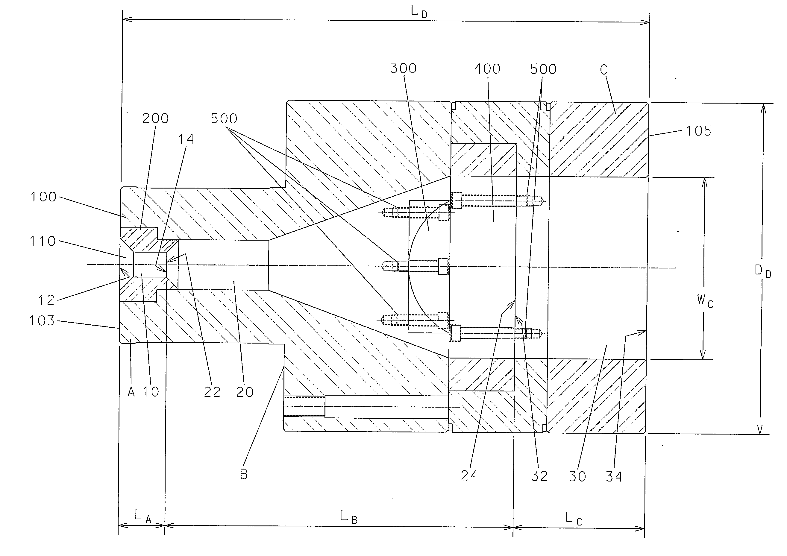
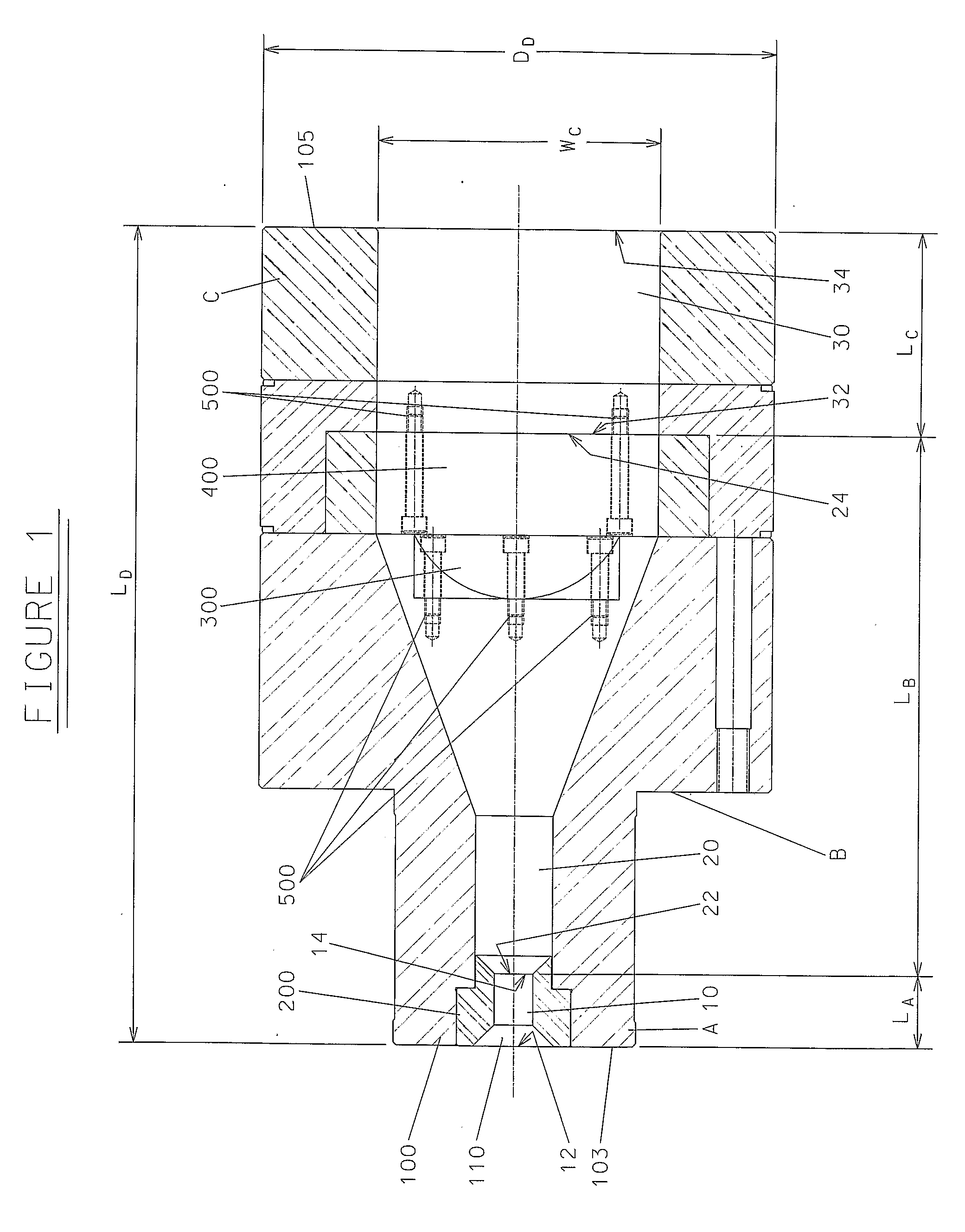
[0073]The die has a length LD of 16 inches (406 mm) and a diameter at its exit end of 10 inches (254 mm). The length LA of the Flow Restriction Zone A is 1.4 inches (3.6 cm) The length LB of Flow Redistribution Zone B is 10.6 inches (26.9 cm) The length LC of Land Zone C is 4 inches (10 cm).

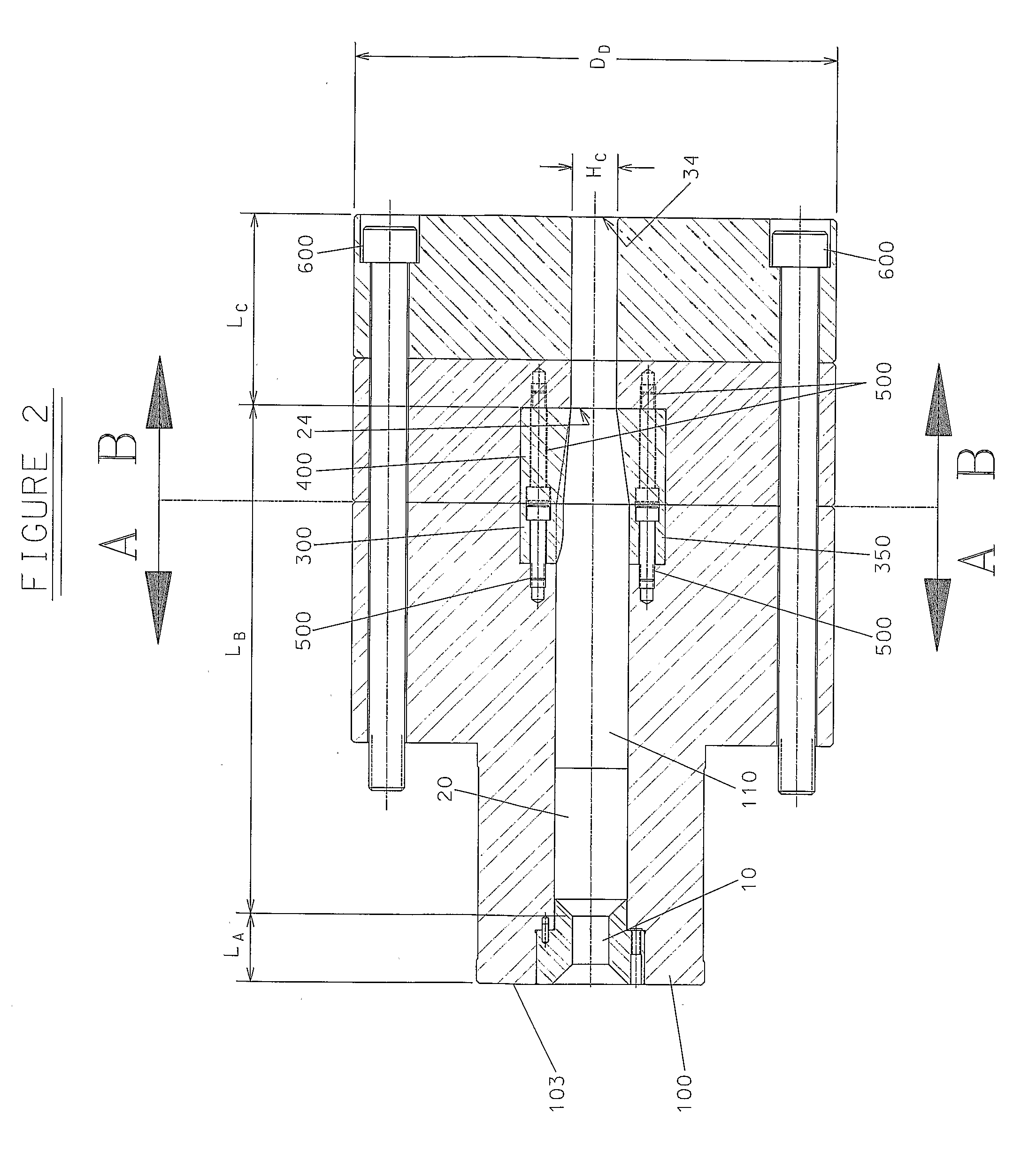
[0074]The die has an entrance orifice 12 that is 1.57 inches (40 mm) in diameter. Exit orifice 14 has a diameter of 0.75 inches (19 mm). Redistributive Flow Channel 20 symmetrically flares to a diameter of 1.5 inches (38 mm) before becoming rectangular. Land Channel 30 has a width, WC, of 5.50 inches (140 mm) and a height, HC, of 0.94 inches (24 mm). Elements 300 and 310 reduce the height of Redistributive Flow Channel 20 and are 3.3 inches (8.4 cm) long. Elements 300 and 400 protrude into Redistributive Flow Channel 20 with a symmetrical bulge (half dog-bone profile) centered across the Channel's width and having a maximum protrusion corresponding to a 4 inch (10 cm) wide portion of a 14.5 inch ...

example 2

[0078]Prepare Example 2 using the formulation and process of Example 1, except use an Element 200 in the die that is longer and defines a larger Restrictive Flow Channel than in the die of Example 1. The different Element 200 modifies the die so that the length LA of the Flow Restriction Zone A is 5 inches (13 cm), the length LB of Flow Redistribution Zone B is 7 inches (18 cm) and the Restrictive Flow Zone exit orifice 14 has a diameter of one inch (25 mm).

[0079]The die and process of Example 2 create a board similar to that of Example 1. The die of Example 2 is an example of the die of the present invention and the process of Example 2 is an example of the process of the present invention.


PUM

PropertyMeasurementUnit
Fractionaaaaaaaaaa
Lengthaaaaaaaaaa
Lengthaaaaaaaaaa

Abstract

Prepare an extruded filled polymer composite having a highly disperse and uniformly distributed filler by extruding a filled polymer composite through a die with a Flow Restriction Zone, a Flow Redistribution Zone and a Land Zone. The Flow Restriction Zone is proximate to the extruder and increases polymer melt backpressure in the extruder sufficient to induce high dispersion of the filler but not enough to cause undesirable degradation of the polymer melt components.

Description

CROSS REFERENCE STATEMENT[0001]This application claims the benefit of U.S. Provisional Application No. 60 / 704,360, filed Aug. 1, 2005.BACKGROUND OF THE INVENTION[0002]1. Field of the Invention[0003]The present invention relates to an extrusion die that contains a Flow Restriction Zone, a Flow Redistribution Zone and a Land Zone. The present invention also relates a process that uses the extrusion die to prepare an extruded filled polymer composition having a highly dispersed and uniformly distributed filler.[0004]2. Description of Related Art[0005]Dispersing filler into a polymer matrix, particularly when the filler and polymer are not especially compatible, has historically been challenging. The challenge increases as the amount of filler relative to matrix material increases and as product requirements dictate a highly uniform composition. Manufacturing an extruded composition comprising a hydrophilic filler dispersed in a hydrophobic polymer suffers from such a challenge since th...

Claims


Application Information

Patent Timeline
IPC IPC(8): B29C47/00B29C48/09B29C48/30B29C48/305B29C48/325
CPCB29C47/0004B29C47/0009B29C47/0818B29C47/14B29K2711/14B29K2023/065B29K2105/0032B29K2105/06B29K2105/256B29C47/705B29C48/022B29C48/256B29C48/305B29C48/705B29C48/525B29C48/405B29C48/41B29C48/362B29C48/268B29C48/09B29C48/03
Inventor MALONE, BRUCE A.KOPPI, KURT A.
Owner MALONE BRUCE A
Learn More