Method for the manufacture of highly loadable components by precision forging

Active Publication Date: 2006-06-22
ROLLS ROYCE DEUT LTD & CO KG
View PDF18 Cites 4 Cited by
  • Summary
  • Abstract
  • Description
  • Claims
  • Application Information

AI Technical Summary

Benefits of technology

[0008] The present invention, in a broad aspect, provides a forming method for the manufacture of precision-forged components, in particular compressor or turbine blades for aircraft engines and similar forgings with zones of different volume and stress, which yields precision components which possess at least the required strength properties in the various stress zones, while reducing the manufacturing effort in terms of processing times and costs.
[0011] In concrete terms, a preform with a certain volume distribution or with defined volume zones with certain volume accumulation is produced in a one-step forming operation, namely a casting or sintering process. This preform is finish-forged with a minimum number of forming operations (at least one forging step) at a deformation rate corresponding to the material accumulation in the volume zones to achieve the desired strength properties in the various component stress zones on the basis of the respective structural formation determined by the deformation rate. This method, therefore, provides for efficient manufacture of highly loadable components subject to partially different in-service loads by means of a small number of forming steps and a correspondingly small number of intermediate operations (annealing, deburring, cleaning, surface treatment).

Problems solved by technology

This means, however, that the workpiece is further processed with considerable forming and intermediate processing effort to the final component geometry even if the strength properties desired and the corresponding structure required are achieved with only a few forming operations.
Conversely, it is very likely that the required microstructure is not achieved in certain volume zones with only small volume change and correspondingly low forming action.

Method used


Image

  • Method for the manufacture of highly loadable components by precision forging
  • Method for the manufacture of highly loadable components by precision forging

Examples


Embodiment Construction

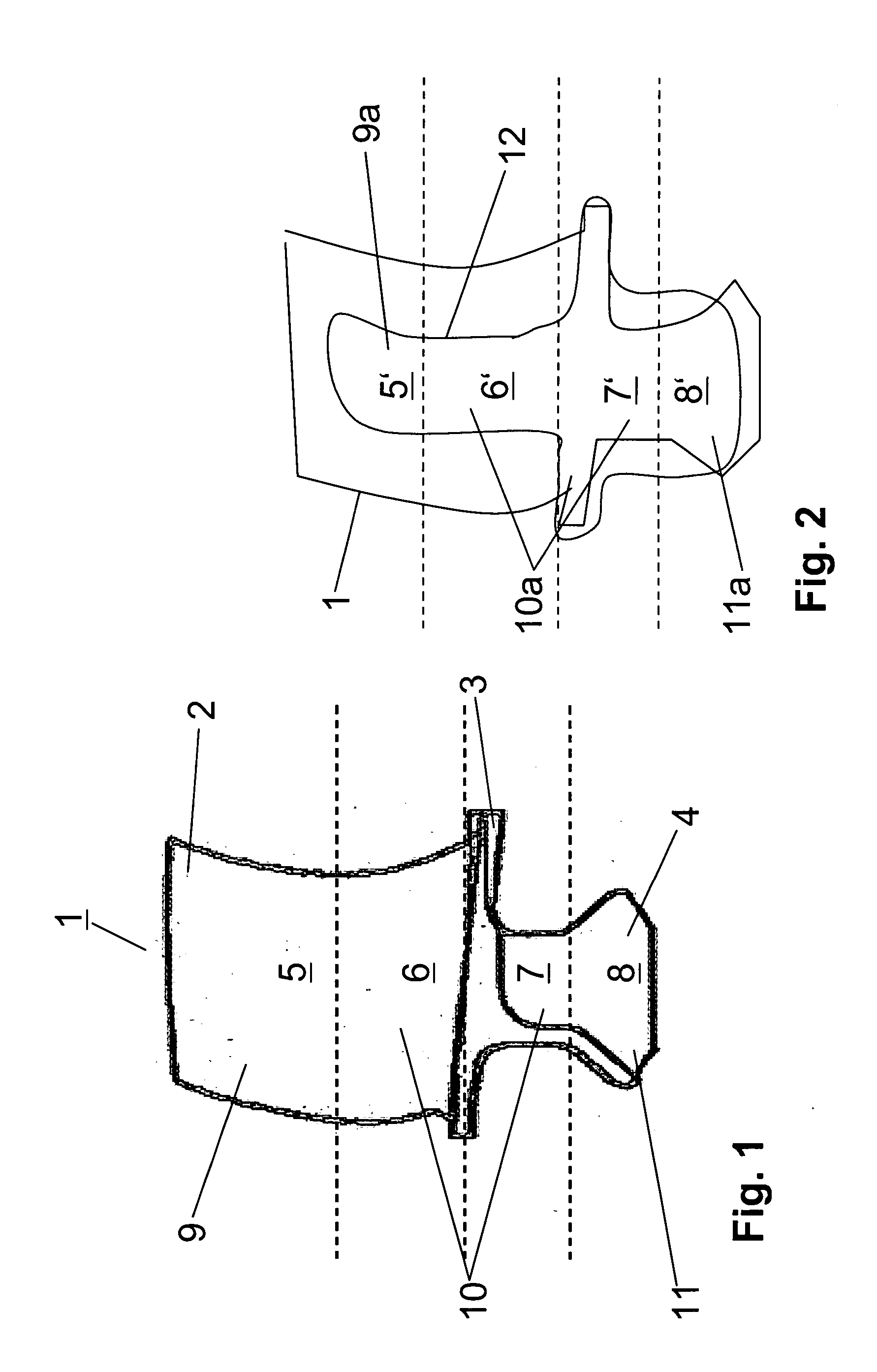
[0015] The finished compressor blade 1 shown in FIG. 1 comprises an airfoil 2, a platform 3 and a root 4. In operation, the compressor blade 1 is partially, i.e., in the various blade zones, subject to different loads. A first stress zone 5 with small volume, which covers approximately the upper airfoil half extending from the blade tip, is subject to a dynamic high-frequency load and a low static load. A second stress zone 6, which covers approximately the bottom airfoil half, has a large volume and is subject to a medium static load and a low-frequency dynamic load. A third stress zone 7, which covers the platform 3 and the adjacent upper part of the root 4, again has a large volume and is subject to a high static and a low dynamic load. A fourth stress zone 8, which covers the bottom part of the root 4, has a medium volume and is subject to low load. The compressor blade 1 accordingly comprises three volume zones 9 to 11 of which each has a different volume, namely a first volume...


PUM

PropertyMeasurementUnit
Structureaaaaaaaaaa
Deformation enthalpyaaaaaaaaaa

Abstract

A method for the manufacture of highly loadable components by precision forging, e.g., of gas turbine compressor blades with different stress zones, initially provides for the production of a preform in a one-step forming operation, e.g., casting or sintering, with further deformable volume zones with a certain volume concentration in the highly loaded areas. The preform is subsequently finish-forged at a deformation rate which is limited by the respective volumes and is merely directed to the load and strength-specific recrystallization and structural requirements in the critical stress zones of the component.

Description

[0001] This application claims priority to German Patent Application DE 10 2004 062 174.8 filed Dec. 17, 2004, the entirety of which is incorporated by reference herein. BACKGROUND OF THE INVENTION [0002] This invention relates to a method for the manufacture of highly loadable components by precision forging, preferably compressor or turbine blades or similar components with different stress and volume zones. [0003] Turbine or compressor blades for aircraft engines are, as is generally known, manufactured by hot forging a blank made of usually cylindrical starting material to a near-net-shape preform in a multitude of subsequent forming operations, if applicable with intermediate deburring and surface treatment, as well as heat treatment to re-crystallization. From the preform, which in this case already comprises an airfoil, a platform and a blade root, the final form of the blade is then produced in further processing operations, for example deburring, cleaning, cold forging or s...

Claims


Application Information

Patent Timeline
IPC IPC(8): B21J5/00
CPCB21J5/02B21K3/04Y10T29/49988Y10T29/49776Y10T29/49771B23P15/02
Inventor ROTH-FAGARASEANU, DAN
Owner ROLLS ROYCE DEUT LTD & CO KG
Why Eureka
Try Eureka