Wireless communication system, base station device, mobile station device, and macrodiversity selection method
a technology of wireless communication and macrodiversity, which is applied in the field of wireless communication system, mobile station device, and macrodiversity selection method, can solve the problems of deterioration of the received signal, inability to realize the requested transmission rate, and inability to transmit signals from other sectors, so as to prevent interference by signals transmitted from other sectors, improve the system throughput of a system having a plurality of cells, and improve the reception strength of signals
- Summary
- Abstract
- Description
- Claims
- Application Information
AI Technical Summary
Benefits of technology
Problems solved by technology
Method used
Image
Examples
first embodiment
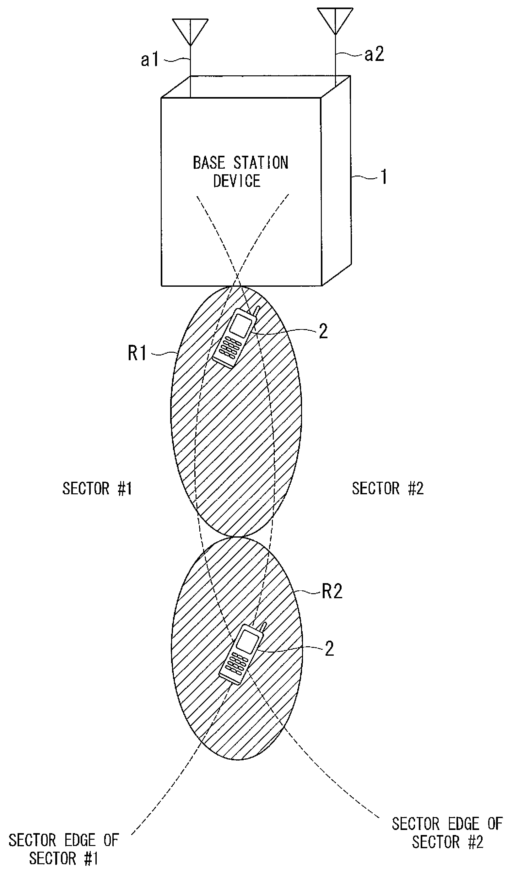
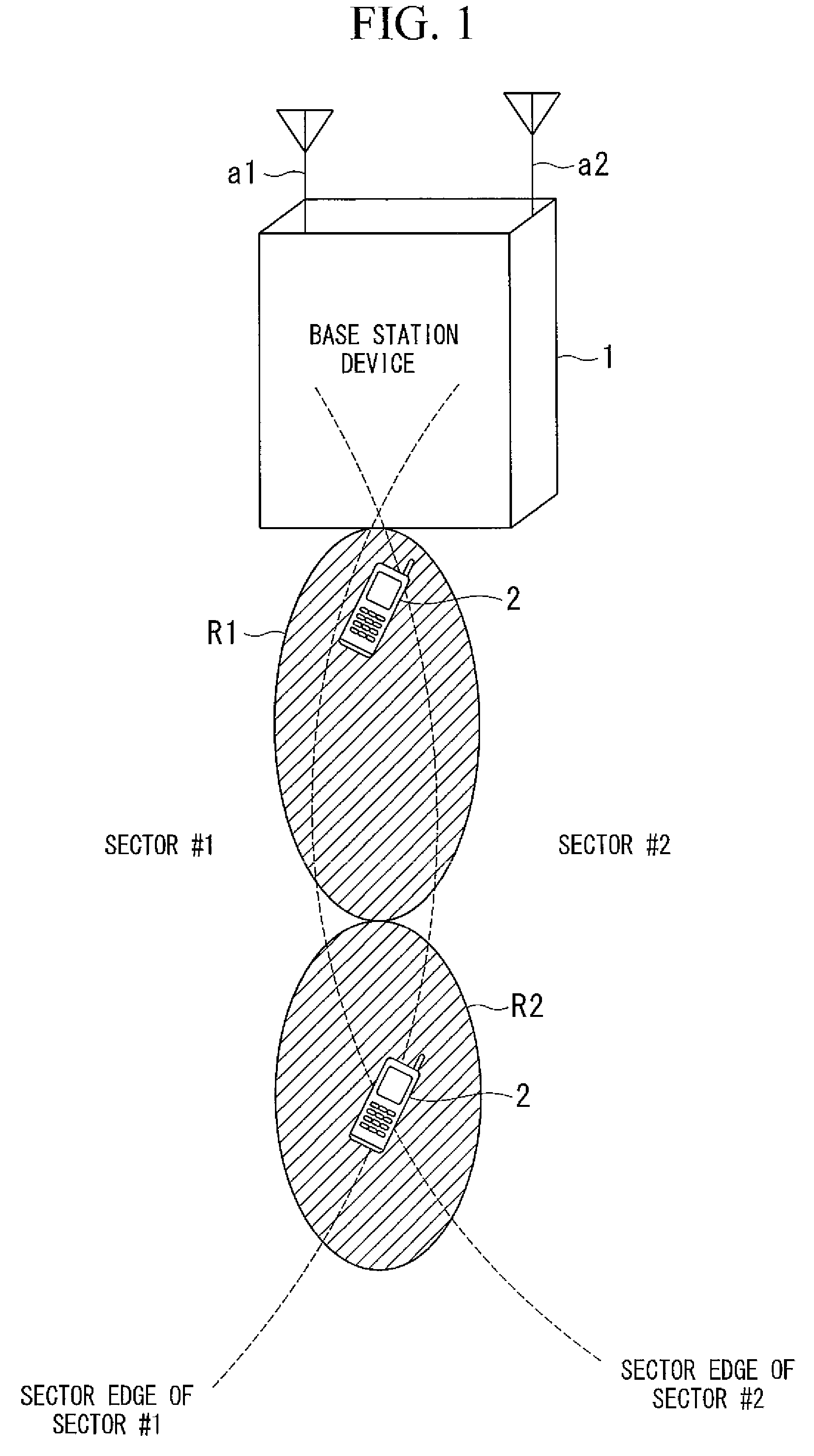
[0096]FIG. 1 is a conceptual view of a macrodiversity selection method according to a first embodiment of the invention. In this embodiment, when a mobile station device 2 is located at a sector edge, which is a region at the interface between sector #1, which is a region that transmits a signal from antenna a1, and sector #2, which is a region that transmits a signal from antenna a2, in a region R1 (sector edge near cell center) where the distance between the mobile station device 2 and a base station device 1 is less than a predetermined threshold, fast sector selection with transmission muting is employed. When the mobile station device 2 is located in a region R2 near the cell edge (sector edge near cell edge) where the distance between it and the base station device 1 is greater than the predetermined threshold, soft-combining is employed. A sector edge is a region at the interface between two sectors (regions R1 and R2 in FIG. 1). A cell edge is a region at the interface betwe...
second embodiment
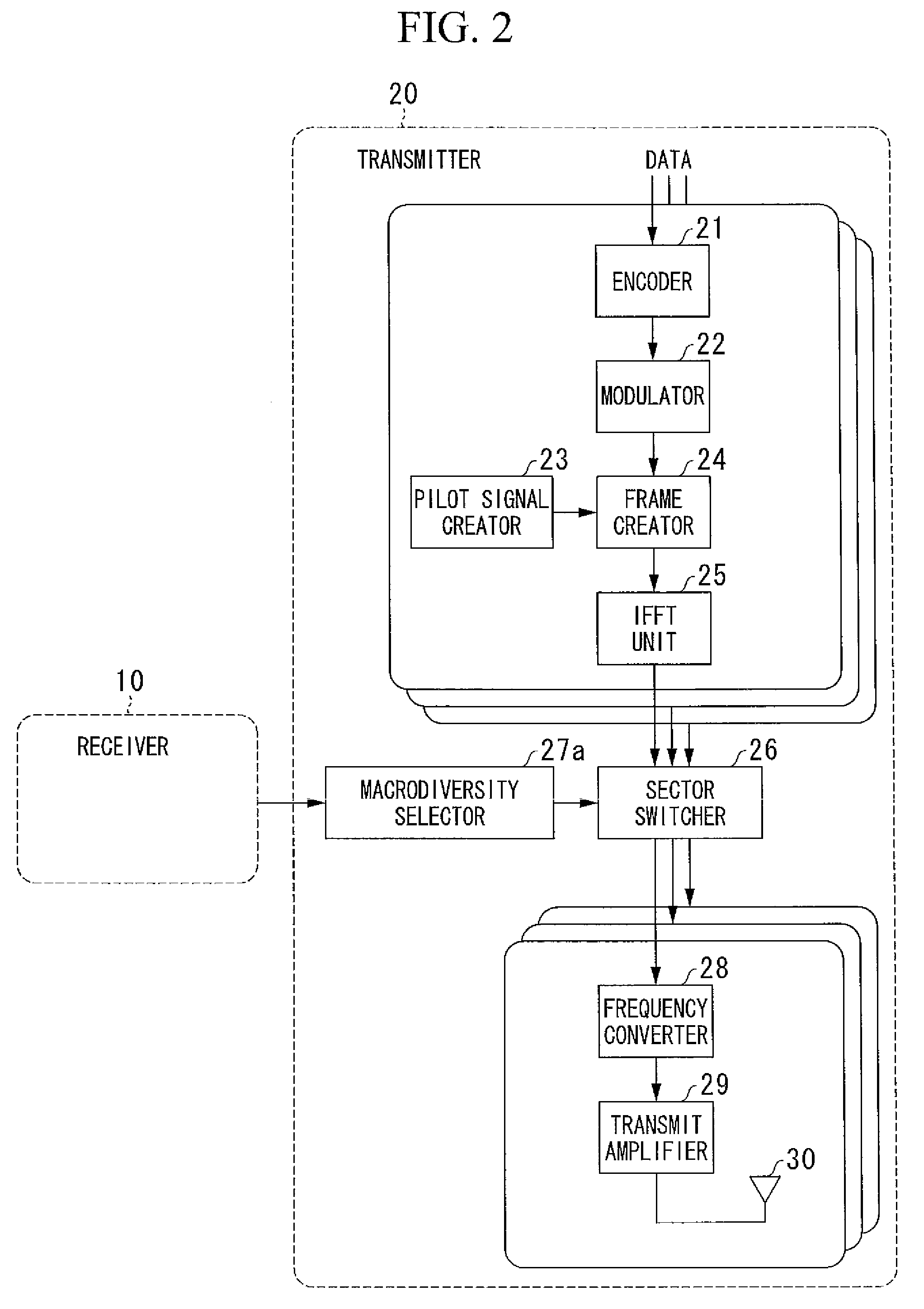
[0117]FIG. 5 is a block diagram of the configuration of a base station device according to a second embodiment of the invention. Like parts to those of the configuration of the base station device according to the first embodiment (FIG. 2) are denoted by like reference numerals and are not repetitiously explained. Points of difference with the base station device 1 according to the first embodiment are that positional information is not fed back by the mobile station device 2, and that the processing content of a macrodiversity selector is different. Based on the reception power or the received SINR, a macrodiversity selector 27b determines whether to use macrodiversity between sectors, selects a macrodiversity method for use, and outputs sector selection control information.
[0118]FIG. 6 is a block diagram of the configuration of a mobile station device according to the second embodiment. Like parts to those of the configuration of the mobile station device according to the first em...
third embodiment
[0148]Subsequently, a macrodiversity selection method according to a third embodiment of the invention will be explained.
[0149]Since the configurations of a base station device 1 and a mobile station device 2 are the same as the base station device 1 (FIG. 5) and the mobile station device 2 (FIG. 6), they are not explained further.
[0150]FIG. 10 is a flowchart of the flow of processes of a macrodiversity selection method according to a third embodiment of the invention. Points of difference from the processes of the macrodiversity selection method according to the second embodiment (FIG. 9) are that, in a step W5 corresponding to step V5, it is determined whether the mobile station device 2 is near to or far from the sector edge by determining whether the received SINR of the self sector is greater than a predetermined threshold N1, and that, in a step W6 corresponding to step V6, it is determined whether the mobile station device 2 is near to or far from the sector edge by determini...
PUM
 Abstract
Description
Claims
Application Information
 - R&D
- Intellectual Property
- Life Sciences
- Materials
- Tech Scout
- Unparalleled Data Quality
- Higher Quality Content
- 60% Fewer Hallucinations
Browse by: Latest US Patents, China's latest patents, Technical Efficacy Thesaurus, Application Domain, Technology Topic, Popular Technical Reports.
© 2025 PatSnap. All rights reserved.Legal|Privacy policy|Modern Slavery Act Transparency Statement|Sitemap|About US| Contact US: help@patsnap.com


