
Photovoltaic Roofing Elements Including Tie Layer Systems, And Roofs Using Them, And Methods For Making Them

Active Publication Date: 2009-05-28
CERTAIN TEED LLC
View PDF35 Cites 84 Cited by
  • Summary
  • Abstract
  • Description
  • Claims
  • Application Information

AI Technical Summary

Benefits of technology

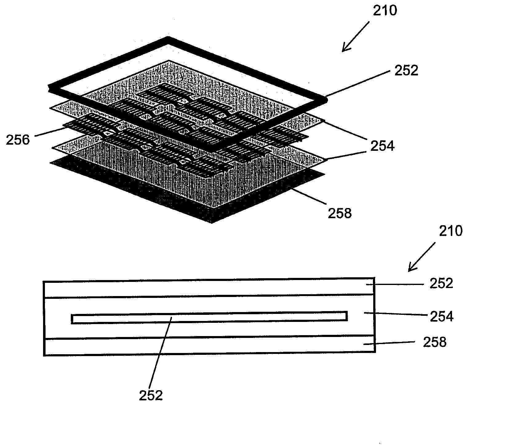
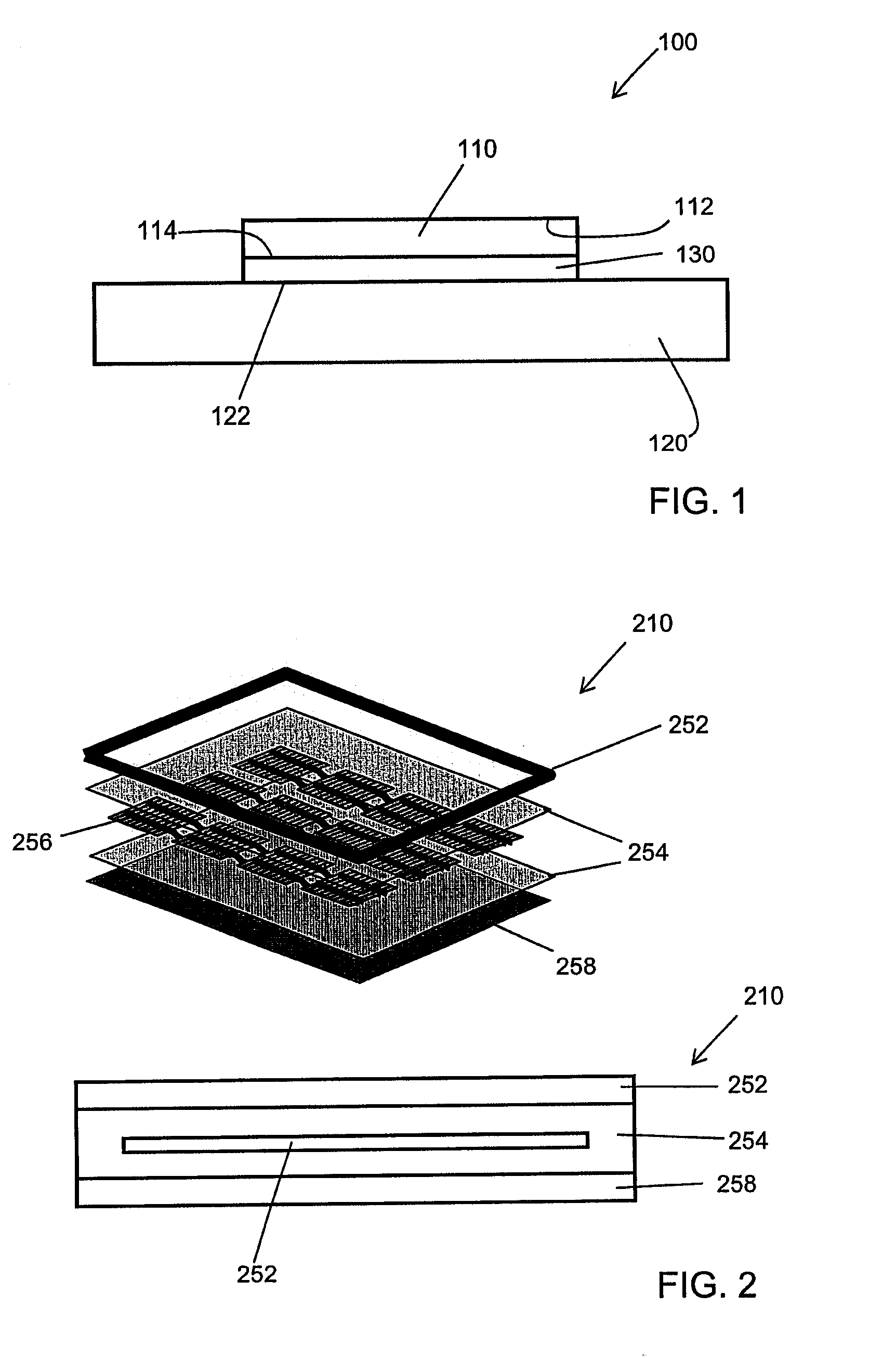
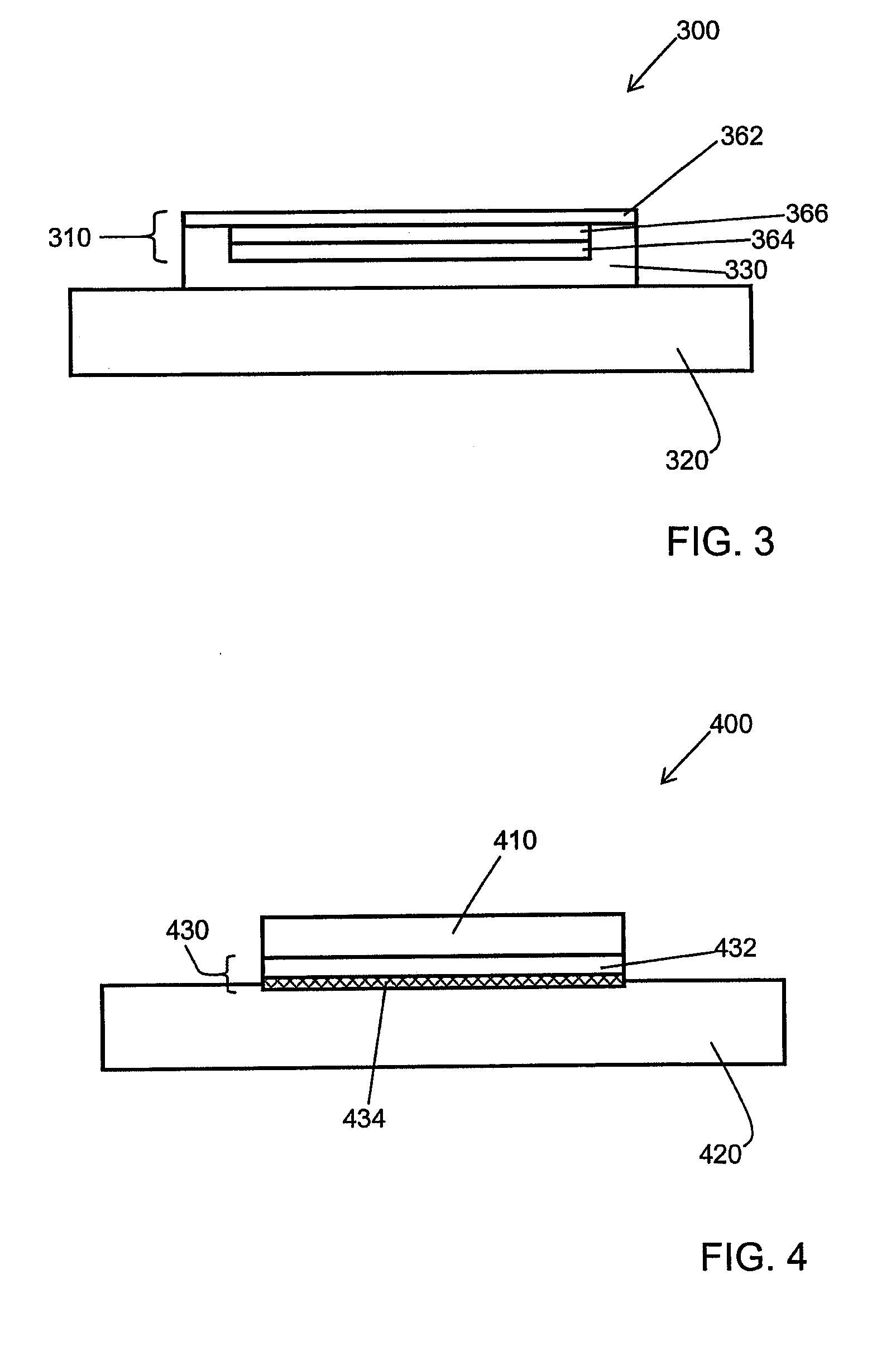
[0031]The photovoltaic roofing elements, roofs and methods of the present invention can result in a number of advantages over prior art methods. For example, the photovoltaic roofing elements of the present invention can provide enhanced adhesion between the photovoltaic element and the roofing substrate.

Problems solved by technology

First, fossil fuels have become increasingly expensive due to increasing scarcity and unrest in areas rich in petroleum deposits.
Second, there exists overwhelming concern about the effects of the combustion of fossil fuels on the environment due to factors such as air pollution (from NOx, hydrocarbons and ozone) and global warming (from CO2).
However, in many circumstances, formation of a long-lived physical connection between the material of the encapsulated photovoltaic element and the material of a substrate can be difficult, especially when the materials used to make the encapsulated photovoltaic element have low surface tension.
Moreover, adhesion between photovoltaic elements and substrates can be problematic even when the photovoltaic element is not encapsulated, especially around the periphery of the photovoltaic element.

Method used


Image

  • Photovoltaic Roofing Elements Including Tie Layer Systems, And Roofs Using Them, And Methods For Making Them
  • Photovoltaic Roofing Elements Including Tie Layer Systems, And Roofs Using Them, And Methods For Making Them
  • Photovoltaic Roofing Elements Including Tie Layer Systems, And Roofs Using Them, And Methods For Making Them

Examples


example 1

[0077]Tie layer substrate materials that can bond to both to an encapsulated photovoltaic element and a polyolefin roofing substrate were studied by extruding tie layers directly on to the substrate in a extrusion / lamination machine. The substrate used in this example was polypropylene (Basell PP KS02, available from Basell Corp., Elkton, Md.) containing 30 wt % of calcium carbonate as filler. The substrate was extruded as a sheet using a Johnson 2″ diameter extruder in combination with a 26″ die using processing temperatures of the barrel at 370° F., die temperature at 350° F., roll temperature at 113° F., and screw speed at 35 rpm to a layer thickness of about 20 mil.

[0078]In a first stage experiment, the adhesion between various tie layer systems and the propylene substrate was studied by the using the same extruder to extrude tie layer system materials at a layer thickness in the range of about 6-10 mil. The adhesion was then evaluated by a T-peel test (ASTM D-1876) using an Ins...

example 2

[0080]An encapsulated photovoltaic element affixed to a tie layer system was constructed by first laminating a top protective layer of ETFE film (TEFZEL from DuPont), an encapsulant layer of EVA (Elvax 3185 from DuPont Corp.), a photovoltaic cell (T-cell available from Uni-Solar Corp., Auburn Hill, Mich.), a back encapsulant layer of the same EVA, and a tie layer system consisting of a single layer of 30 wt % EVA (DuPont Bynel E418) and 70% polypropylene (Basell KS021P) using the same extruder as in Example 1. Once the multi-layer structure was fabricated, the assembly was then joined to a polypropylene substrate (#2898K13—¼″ thick sheet stock available from McMaster-Carr Corp, New Brunswick, N.J.) using an ultrasonic welding technique. The ultrasonic welding was performed using a Branson 2000X system with 2.5 KW max power output on a sample piece of 5″×5″. Good adhesion was found to be achieved around the perimeter of the sample piece by using 50% power setting and 20,000 Hertz fre...


PUM

PropertyMeasurementUnit
Thicknessaaaaaaaaaa
Thicknessaaaaaaaaaa
Heightaaaaaaaaaa

Abstract

The present invention relates generally to photovoltaic devices. The present invention relates more particularly to photovoltaic roofing products in which a photovoltaic element is joined to a roofing substrate. In one embodiment, the present invention provides a photovoltaic roofing element comprising: an encapsulated photovoltaic element having a top surface and a bottom surface, a top layer material at its top surface and a bottom layer material at its bottom surface; a roofing substrate having a top surface; and a tie layer system disposed between the encapsulated photovoltaic element and the roofing substrate and joining the bottom surface of the encapsulated photovoltaic element to the top surface of the roofing substrate.

Description

CROSS-REFERENCE TO RELATED APPLICATIONS[0001]This application claims priority under 35 U.S.C. § 119(e) to U.S. Provisional Patent Applications Ser. No. 60 / 985,932, filed Nov. 6, 2007; Ser. No. 60 / 985,935, filed Nov. 6, 2007; and Ser. No. 60 / 986,556, filed Nov. 8, 2007 each of which is hereby incorporated herein by reference in its entirety.BACKGROUND OF THE INVENTION[0002]1. Field of the Invention[0003]The present invention relates generally to photovoltaic devices. The present invention relates more particularly to photovoltaic roofing products in which a photovoltaic element is joined to a roofing substrate.[0004]2. Summary of the Related Art[0005]The search for alternative sources of energy has been motivated by at least two factors. First, fossil fuels have become increasingly expensive due to increasing scarcity and unrest in areas rich in petroleum deposits. Second, there exists overwhelming concern about the effects of the combustion of fossil fuels on the environment due to ...

Claims


Application Information

Patent Timeline
IPC IPC(8): E04D13/18H01L31/048B32B37/14E04C2/00E04C2/26
CPCY02B10/12H02S20/23Y10T156/10Y02E10/50Y02B10/10
Inventor SHIAO, MING-LIANGKALKANOGLU, HUSNU M.SHAW, WAYNE E.JACOBS, GREGORY F.
Owner CERTAIN TEED LLC
Learn More