Method for forming diamond-like carbon film
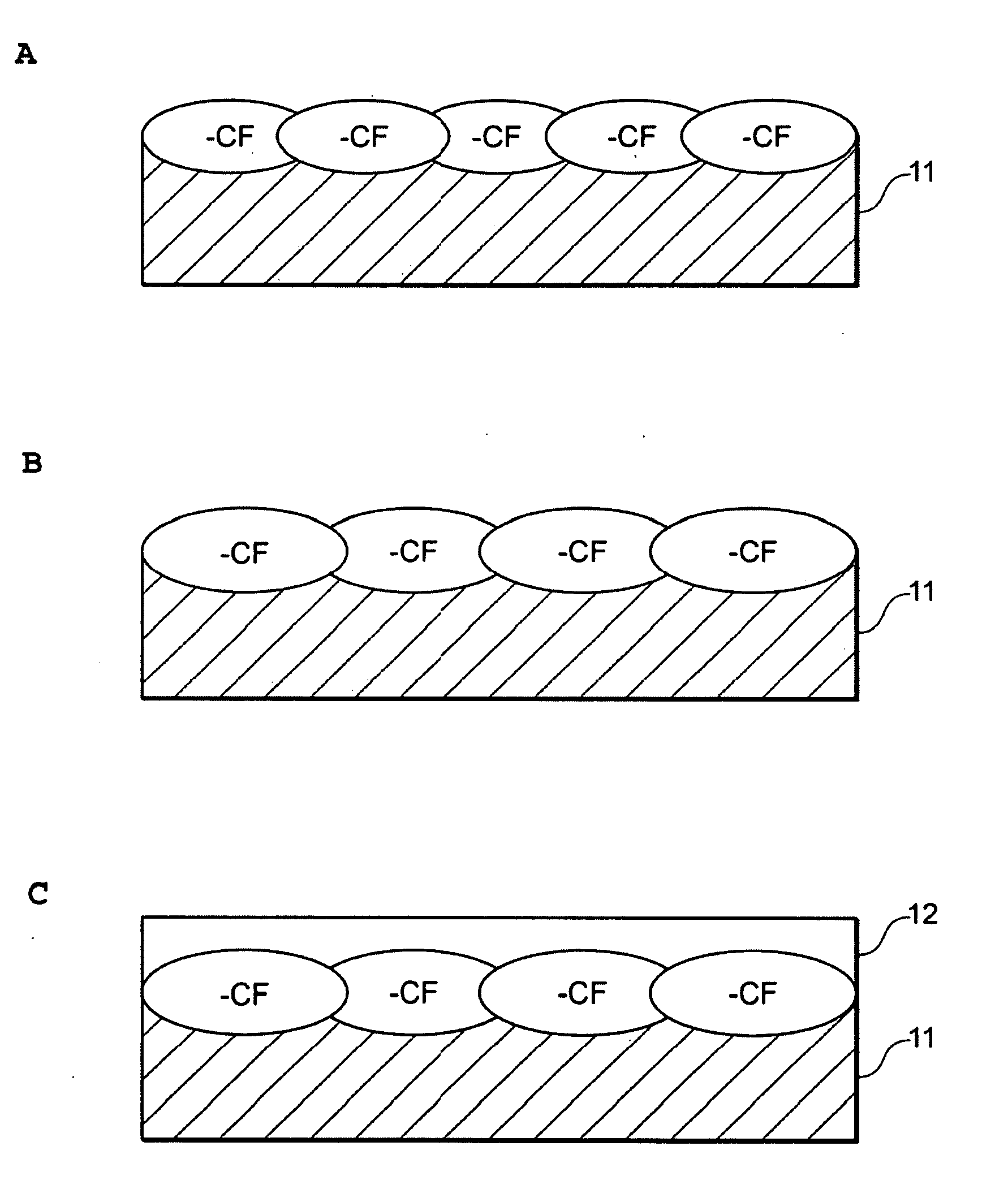
a diamond-like carbon and film technology, applied in the field of diamond-like carbon film forming, can solve the problems of low adhesion strength of diamond-like carbon film relative to polymeric materials and metallic materials, complex treatment process, and inability to remove materials, so as to achieve simple steps and enhance the adhesion strength of diamond-like carbon film relative to polymeric materials and metal materials
- Summary
- Abstract
- Description
- Claims
- Application Information
AI Technical Summary
Benefits of technology
Problems solved by technology
Method used
Image
Examples
example 1
[0081]Surface modification treatment was conducted by plasma radiation on a substrate (length: 10 mm×width: 10 mm×thickness: 3 mm) made of PTFE (Naflon sheet TOMBO-9000 manufactured by NICHIAS Corporation), and then a DLC film was formed on the substrate. After the surface modification treatment, an X-ray photoelectron spectroscopy measurement and a contact angle test were conducted on the substrate before forming the DLC film in order to measure the effect of the surface modification treatment. The adhesion strength and abrasion resistance of the DLC film were evaluated by a tape test, a tensile test and a ball-on disk test.
Preparation of Test Piece
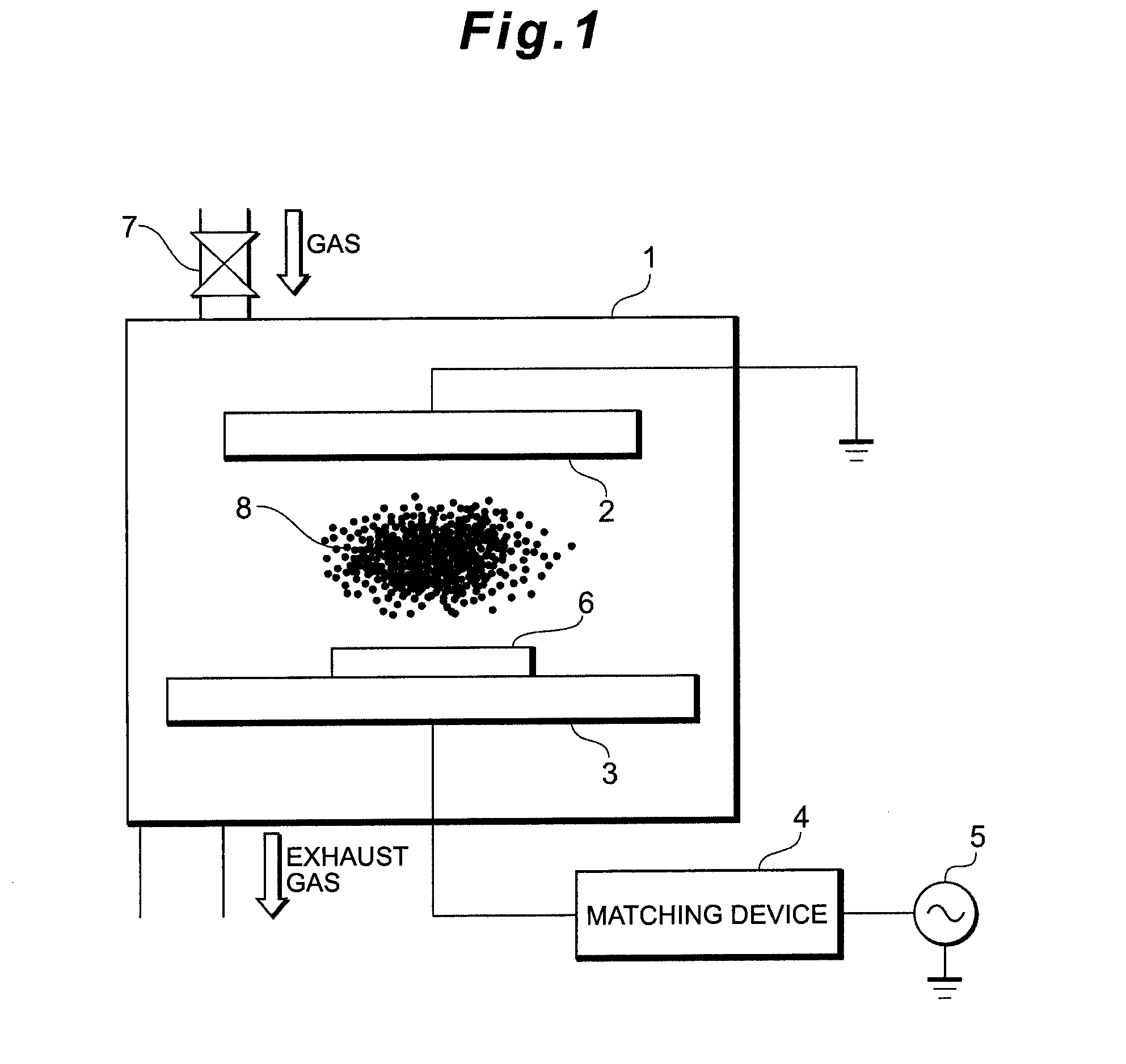
[0082]The substrate made of the PTFE was placed in a chamber in a high-frequency plasma CVD apparatus (PED-301 manufactured by Canon ANELVA Corporation), the chamber was put into a vacuum state (to 0.01 Pa or lower), then reaction gas was introduced at a gas flow rate of 45 sccm, and plasma was generated under the below conditions to mod...
example 2
[0117]Surface modification treatment was conducted by plasma radiation on a substrate (length: 10 mm×width: 10 mm×thickness: 1 mm) made of stainless steel (SUS316 manufactured by NIKORA KABUSIKIGAISHA) using the same conditions and procedure as those in example 1, and then a DLC film was formed. Like in example 1, an XPS measurement, a contact angle test, a tape test, a tensile test and a ball-on disk test were conducted.
XPS Measurement
[0118]The surface of the stainless steel substrate after the surface modification treatment and before the formation of the DLC film was measured by XPS under the same condition as that in example 1.
[0119]FIG. 16 shows diagrams showing the result of the XPS measurement for a stainless steel substrate surface-modified by the O2 plasma treatment, a stainless steel substrate surface-modified by the N2 plasma treatment and a surface-unmodified stainless steel substrate. FIG. 16(a) shows an Fe2p spectrum, FIG. 16(b) shows an O1s spectrum, FIG. 16(c) shows ...
example 3
[0139]Surface modification treatment was conducted by plasma radiation on a substrate (length: 10 mm×width: 10 mm×thickness: 1 mm) made of NiTi (manufactured by THE FURUKAWA ELECTRIC CO., LTD.) using the same conditions and procedure as those in example 1, and then a DLC film was formed. Like in example 1, an XPS measurement, a contact angle test, a tape test, a tensile test and a ball-on disk test were conducted.
XPS Measurement
[0140]The surface of the NiTi substrate after the surface modification treatment and before the formation of DLC film was measured by XPS under the same conditions as in example 1.
[0141]FIG. 26 shows diagrams showing the results of the XPS measurement for a NiTi substrate surface-modified by the O2 plasma treatment, a NiTi substrate surface-modified by the N2 plasma treatment and an untreated NiTi substrate that was not subjected to surface modification treatment. FIG. 26(a) shows a Ti2p spectrum, FIG. 26(b) shows a Ni2p spectrum, FIG. 26(c) shows an O1s spec...
PUM
| Property | Measurement | Unit |
|---|---|---|
| Adhesion strength | aaaaa | aaaaa |
| Metallic bond | aaaaa | aaaaa |
Abstract
Description
Claims
Application Information
 - R&D
- Intellectual Property
- Life Sciences
- Materials
- Tech Scout
- Unparalleled Data Quality
- Higher Quality Content
- 60% Fewer Hallucinations
Browse by: Latest US Patents, China's latest patents, Technical Efficacy Thesaurus, Application Domain, Technology Topic, Popular Technical Reports.
© 2025 PatSnap. All rights reserved.Legal|Privacy policy|Modern Slavery Act Transparency Statement|Sitemap|About US| Contact US: help@patsnap.com


