
Band-gap reference voltage generator for low-voltage operation and high precision

a reference voltage and low-voltage technology, applied in the direction of electric variable regulation, process and machine control, instruments, etc., can solve the problems of band-gap bias circuit, deviating from constant value of bias voltage provided by a typical bias circuit, and difficult to fabricate them to have exactly the same characteristics

Inactive Publication Date: 2009-05-21
ELECTRONICS & TELECOMM RES INST +1
View PDF6 Cites 24 Cited by
  • Summary
  • Abstract
  • Description
  • Claims
  • Application Information

AI Technical Summary

Benefits of technology

[0025]The present invention is directed to a band-gap reference voltage generator for low-voltage operation and high precision, which is capable of providing a stable reference voltage that is unaffected by a change in temperature, in spite of a low power supply voltage of 1V or less used to implement a low voltage design.
[0026]The present invention is also directed to a band-gap reference voltage generator for low-voltage operation and high precision, which is capable of minimizing reference voltage variation caused by offset noise generated from a feedback amplifier to thereby provide a precise reference voltage.

Problems solved by technology

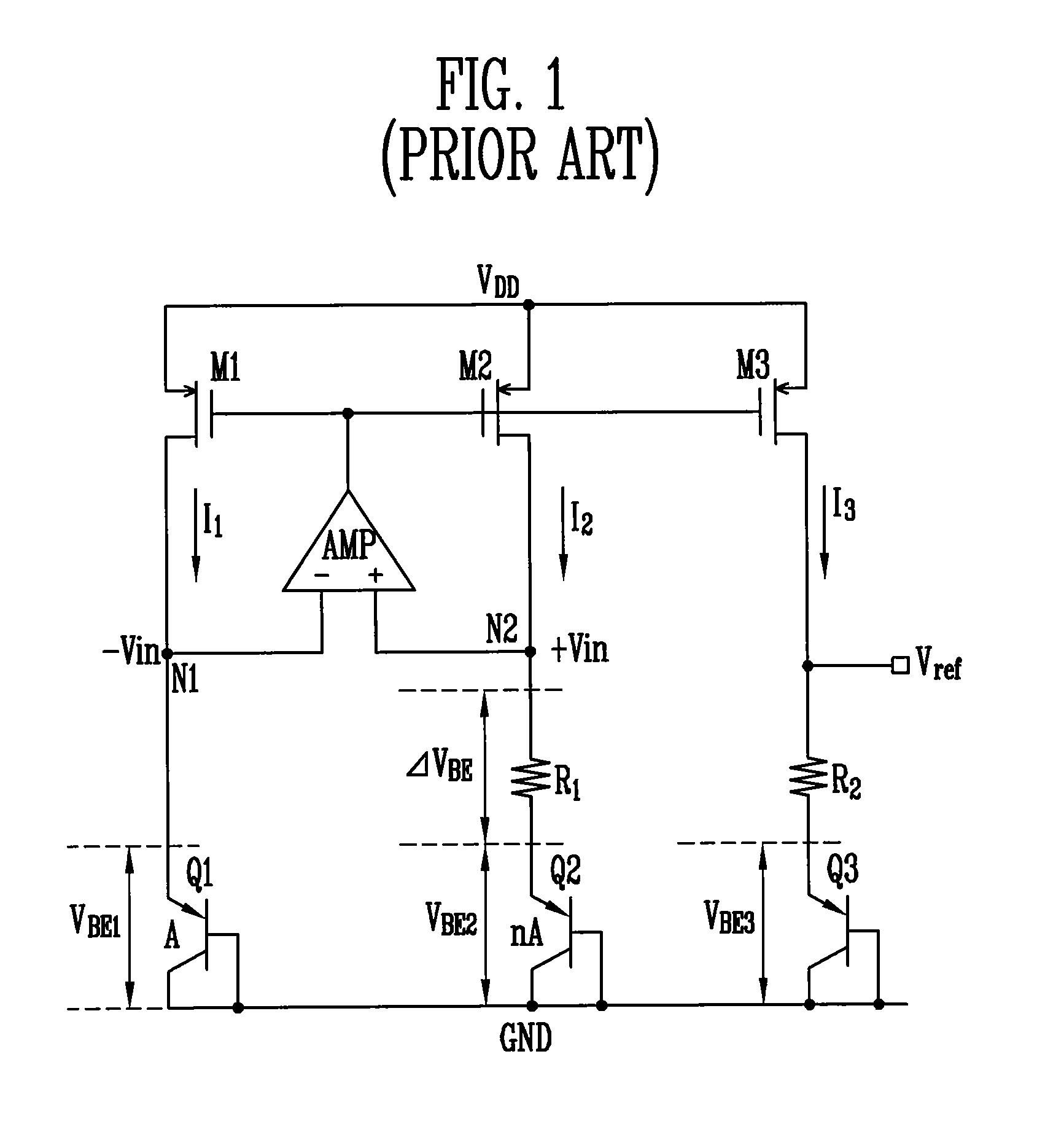
However, the bias voltage provided by a typical bias circuit deviates from a constant value over time due to change in the temperature of the bias circuit during operation.
However, the problem with applying a low supply voltage for the low-power consumption design is that a band-gap bias circuit functioning as a core in the chip needs a working power supply of at least 1.5V, as described above.
Although the two CMOS transistors have identical designs, it is difficult to fabricate them to have exactly the same characteristics due to process fluctuations.

Method used


Image

  • Band-gap reference voltage generator for low-voltage operation and high precision
  • Band-gap reference voltage generator for low-voltage operation and high precision
  • Band-gap reference voltage generator for low-voltage operation and high precision

Examples


Embodiment Construction

[0037]Hereinafter, exemplary embodiments of the present invention will be described in detail with reference to the accompanying drawings. However, the present invention is not limited to the embodiments disclosed below, but can be implemented in various types. Therefore, the present embodiment is provided for complete disclosure of the present invention and to fully inform the scope of the present invention to those ordinarily skilled in the art.

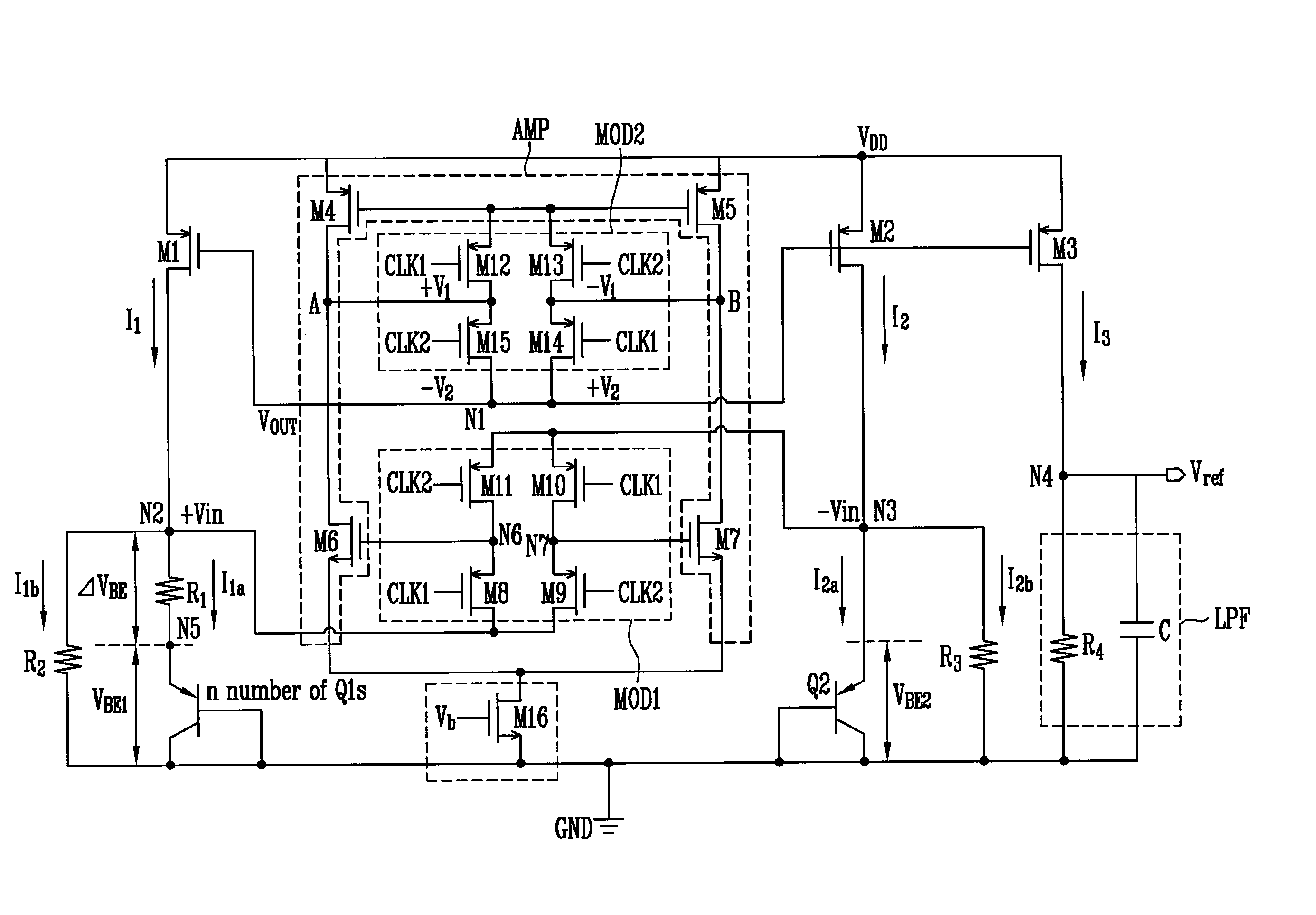
[0038]FIG. 2 is a circuit diagram of a band-gap reference voltage generator for low-voltage operation and high precision according to an exemplary embodiment of the present invention.

[0039]Referring to FIG. 2, the band-gap reference voltage generator for low-voltage operation and high precision according to an exemplary embodiment of the present invention comprises first through third p-channel metal oxide semiconductor (PMOS) transistors M1 through M3, a feedback amplifier AMP that includes fourth and fifth PMOS transistors M4 and M5 and s...


PUM


Abstract

Provided is a band-gap reference voltage generator for low-voltage operation and high precision. The band-gap reference voltage generator minimizes voltage drop by connecting resistors in parallel to bipolar transistors, and cancels temperature dependence by properly adjusting a resistor of an output stage, so that it can provide a stable reference voltage that is unaffected by a change in temperature in spite of a low power supply voltage. Further, the band-gap reference voltage generator minimizes variation of the reference voltage caused by offset noise by switching of input and output voltages at input and output stages of a feedback amplifier, so that it can provide a precise reference voltage.

Description

CROSS-REFERENCE TO RELATED APPLICATION[0001]This application claims priority to and the benefit of Korean Patent Application No. 2007-116509, filed Nov. 15, 2007, the disclosure of which is incorporated herein by reference in its entirety.BACKGROUND[0002]1. Field of the Invention[0003]The present invention relates to a band-gap reference voltage generator for low-voltage operation and high precision, and more particularly, to a band-gap reference voltage generator for low-voltage operation and high precision which is relatively unaffected by offset noise and capable of providing stable reference voltage even at a power supply voltage of 1V or less.[0004]This work was partly supported by the IT R&D program of MIC / IITA [2006-S006-02, Part / Module for ubiquitous terminal].[0005]2. Discussion of Related Art[0006]In general, all analog / radio frequency (RF) or digital circuits integrated into a chip need a stable, precise bias voltage for efficient operation.[0007]However, the bias voltage...

Claims


Application Information

Patent Timeline
IPC IPC(8): G05F1/10
CPCG05F3/30G05F3/24
Inventor ROH, JEONG JINROH, HYUNG DONGKIM, HYOUNG-JOONGKIM, YI GYEONGKWON, JONG KEE
Owner ELECTRONICS & TELECOMM RES INST
Learn More