
Method And Apparatus For Controlling The Flow Of Molten Steel In A Mould

a technology of molten steel and flow, which is applied in the direction of casting apparatus, metal-working apparatus, manufacturing tools, etc., can solve the problems of uncertain and turbulent flow in the mould

Inactive Publication Date: 2009-05-14
ABB (SCHWEIZ) AG
View PDF2 Cites 7 Cited by
  • Summary
  • Abstract
  • Description
  • Claims
  • Application Information

AI Technical Summary

Benefits of technology

[0014]This is achieved by applying a static magnetic field to impart a stabilizing and braking force to a discharge flow from an immersion nozzle when the molten steel flow velocity on the meniscus is higher than the mould powder entrainment critical flow velocity and by controlling the molten steel flow velocity on the molten steel bath surface to a range of from an inclusion adherence critical flow velocity or more to a mould powder entrainment critical flow velocity or less by applying a shifting magnetic field to increase the molten steel flow when the molten steel flow velocity on the meniscus is lower than the inclusion adherence critical flow velocity.
[0017]The stirrer is designed for three phase current which eliminates one cable per phase compared to a two phase system. In case a three phase standard converter is used, the maximum phase current to the coil can also be minimized. A two phase system requires V2 larger phase current in the common return line. The standard converter system for stirrer applications has been modified and also includes the feature to have symmetry in the different phase currents. The higher symmetry achieved in the phase currents the higher performance can be achieved by the stirrer. A normal frequency converter will operate with common phase voltages and as the mutual inductances between the different windings differ, this will result in different phase currents;
[0018]The FC MEMS-design contains a coil capable of creating a static magnetic field for EMDC and a shifting magnetic field for EMLA and EMRS. The shifting magnetic fields for EMLA and EMRS are created by using polyphase AC-currents to feed the coil. Corresponding static magnetic fields will be created by feeding direct current in the different phases and by feeding with different current intensity in the different phases the distribution of the magnetic fields acting on the mould will differ and consequently the braking impact will also differ in different parts of the mould. It may be an advantage to vary the brake effect over time and consequently it is desirable to change the relationship between the DC-currents in the phases over time. Since the time for creating a certain flow pattern is at least 10 seconds, it is desirable to be able to vary the DC-current within said time;

Problems solved by technology

Stirring in a low position will conflict with the flow exiting the nozzle and give an uncertain and turbulent flow in the mould.

Method used


Image

  • Method And Apparatus For Controlling The Flow Of Molten Steel In A Mould
  • Method And Apparatus For Controlling The Flow Of Molten Steel In A Mould
  • Method And Apparatus For Controlling The Flow Of Molten Steel In A Mould

Examples


Embodiment Construction

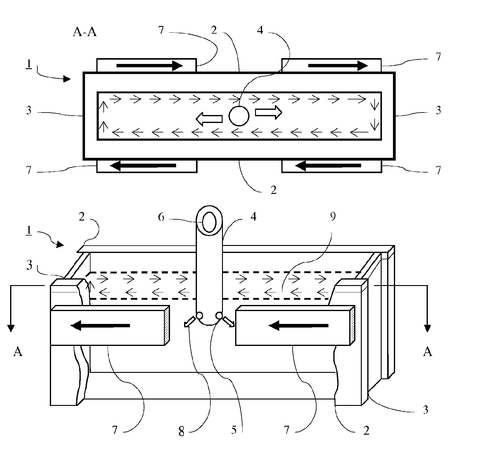
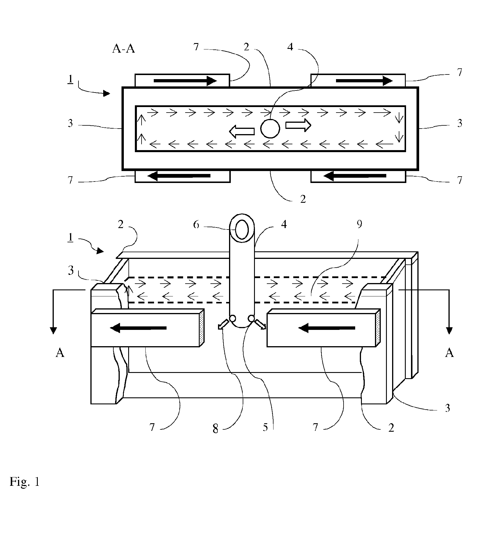
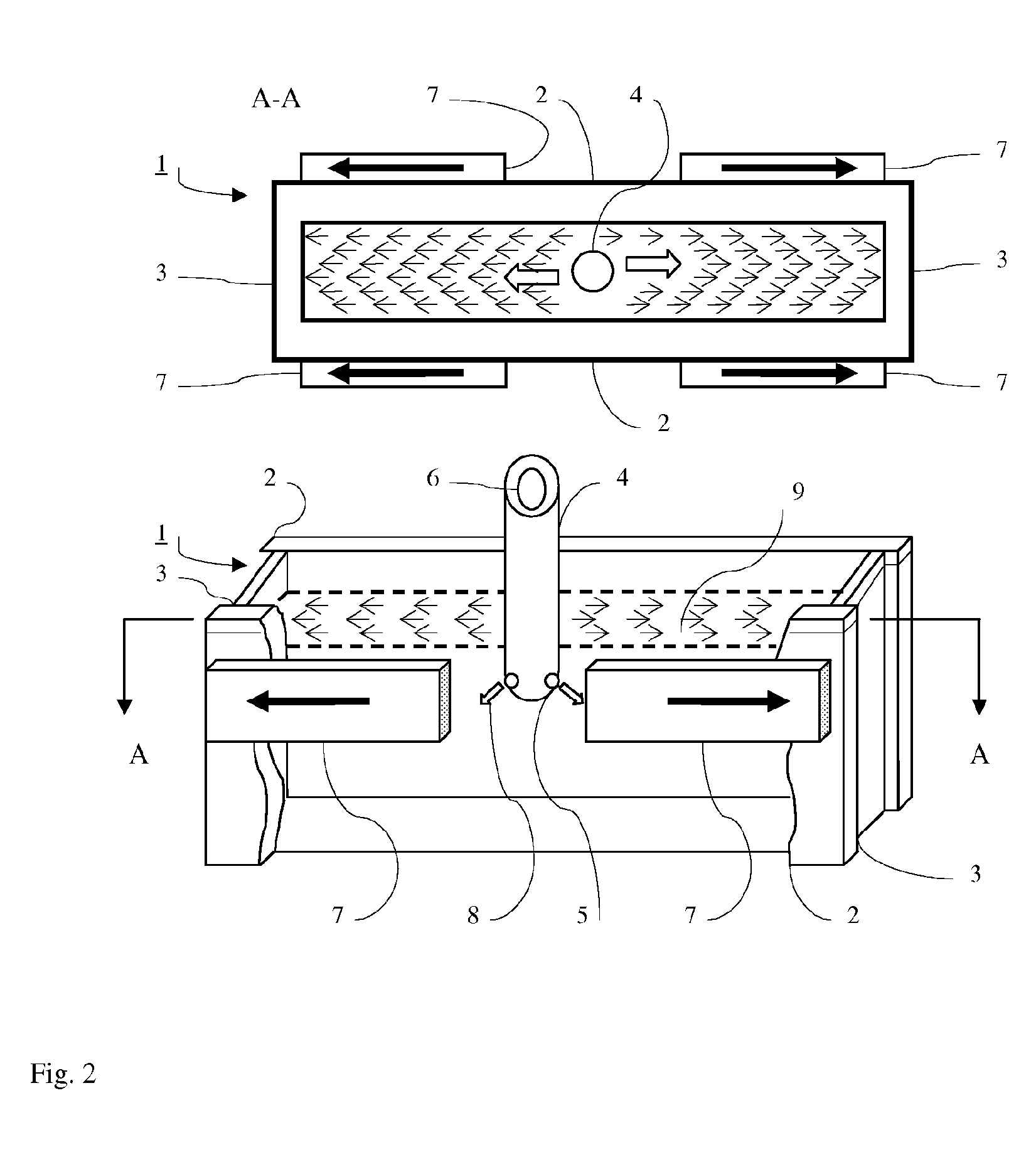
[0024]Embodiments of the present invention will be described herein below with reference to the accompanying drawings. FIGS. 1 and 2 are each schematic views of a continuous slab casting machine used when carrying out the present invention. More specifically, FIGS. 1 and 2 are both schematic perspective / front views of a mold portion according to the present invention.

[0025]Referring to FIG. 1 and 2, a tundish (not shown) is disposed in a predetermined position over a mold (1) that has mutually opposite mold long sides (2) and mutually opposite mold short sides (3) internally provided between the mold long sides (2) . An immersion nozzle (4) having a pair of discharge openings (5) in a lower portion is disposed in contact with an undersurface of a sliding nozzle (not shown) connected to the tundish. A molten steel outflow opening (6) is formed for the molten steel outflow from the tundish to the mold (1). On the rear surfaces of the mold long sides (2), four magnetic field generating...


PUM

PropertyMeasurementUnit
Timeaaaaaaaaaa
Velocityaaaaaaaaaa
Velocityaaaaaaaaaa

Abstract

A method for controlling a flow of molten steel in a mould by applying at least one magnetic field to the molten steel in a continuous slab casting machine. This is achieved by comprising controlling a molten steel flow velocity on a molten steel bath surface, meniscus, to a predetermined molten steel flow velocity by applying a static magnetic field to impart a stabilizing and braking force to a discharge flow from an immersion nozzle when the molten steel flow velocity on the meniscus is higher than a mould powder entrainment critical flow velocity and by controlling the molten steel flow velocity on the meniscus to a range of from an inclusion adherence critical flow velocity or more to a mould powder entrainment critical flow velocity or less by applying a shifting magnetic field to increase the molten steel flow when the molten steel flow velocity on the meniscus is lower than the inclusion-adherence critical flow velocity.

Description

CROSS-REFERENCE TO RELATED APPLICATIONS[0001]The present application is a continuation of pending International patent application PCT / SE2007 / 050489 filed on Jul. 3, 2007 which designates the United States and claims priority from U.S. provisional patent application 60 / 818,527 filed on Jul. 6, 2006, the content of which is incorporated herein by reference.FIELD OF THE INVENTION[0002]The present invention relates to a method and an apparatus for controlling a flow of molten steel in a mould using a continuous slab casting machine, and a method for producing a slab using the flow control method and apparatus.BACKGROUND OF THE INVENTION[0003]One of the quality factors required for a cast product to be produced by a continuous slab casting machine is a reduced amount of inclusions entrapped in the surface layer of the cast product. Such inclusions to be entrapped in the cast product surface layer are, for example:[0004](1) deoxidation products occurring in a deoxidation step using alumi...

Claims


Application Information

Patent Timeline
IPC IPC(8): B22D27/02B22D46/00B22D11/12
CPCB22D11/115B22D27/02B22D11/16
Inventor LEHMAN, ANDERSHACKL, HELMUTERIKSSON, JAN-ERIKSJODEN, OLOF
Owner ABB (SCHWEIZ) AG
Learn More