
Accessing a phase change memory

a phase change memory and memory technology, applied in information storage, static storage, digital storage, etc., can solve the problem of significant current required to program the device, and achieve the effect of increasing the discharge time of the capacitor circui

Active Publication Date: 2009-05-07
OVONYX MEMORY TECH LLC
View PDF2 Cites 68 Cited by
  • Summary
  • Abstract
  • Description
  • Claims
  • Application Information

AI Technical Summary

Benefits of technology

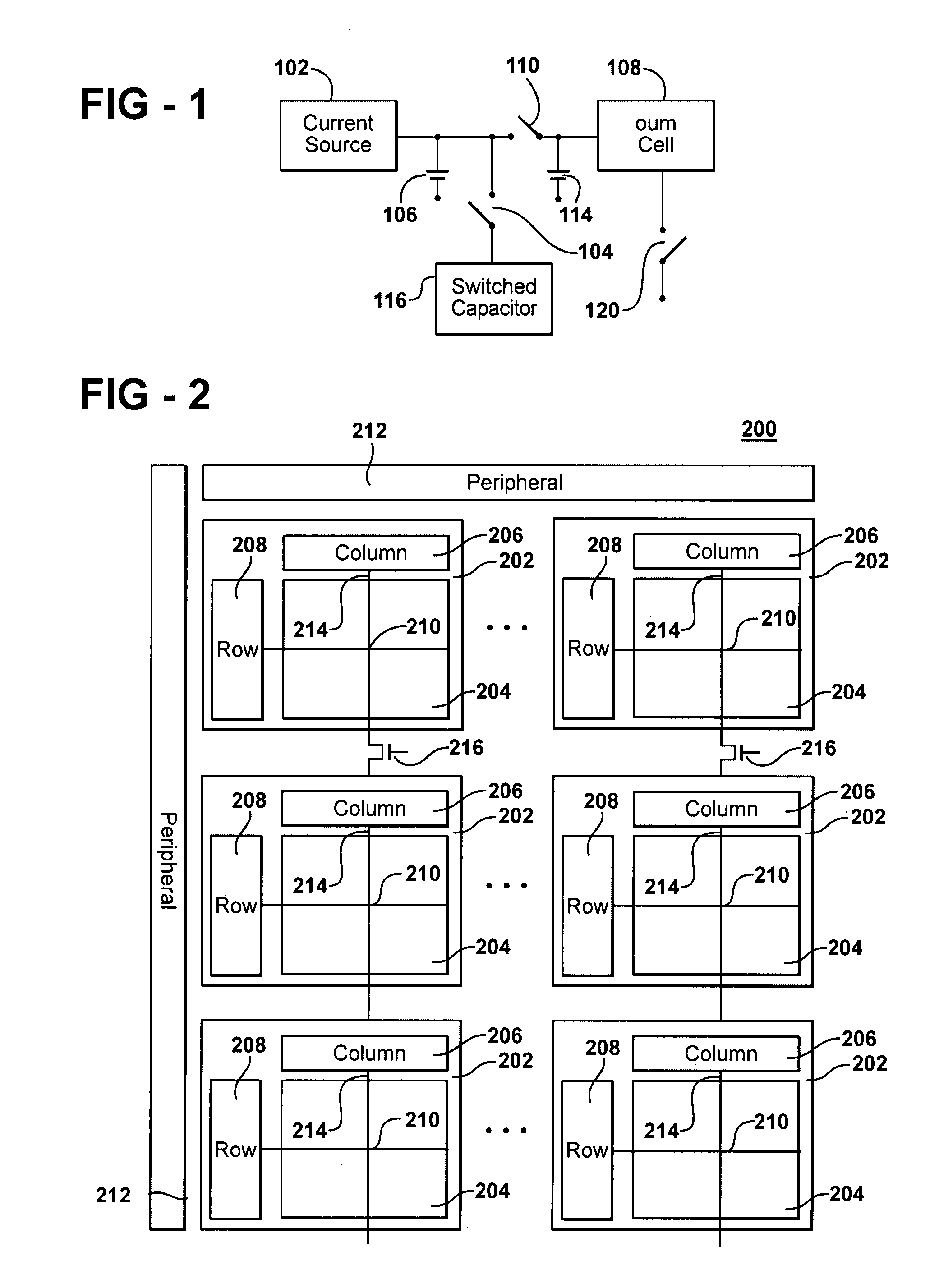
[0016]A single current source may be used to charge an access capacitor for both SET and RESET operations. In both cases a relatively low-level charging current charges the access capacitor. For a SET operation, the access and supplemental capacitor are discharged into the memory cell of interest and the RC time constant of the access capacitor (in combination with the line resistance and contact resistance associated with the phase change memory cell)limits the discharge over an extended period of time to ensure that the memory cell is SET. To further extend this time, the current source may continue to run with a slow turn-off after the memory has thresholded. For a RESET operation, the access is charged and discharged as just described, except that the discharge period is engineered to assure rapid cooling upon termination of the write current, to ensure that the phase change material rapidly cools to the amorphous state. To help assure a fast trailing edge, the supplemental capacitor may be disconnected after discharge, the current source turned off with a fast trailing edge, and / or turning on an active parallel quench transistor to assure a fast trailing edge decay of the column voltage.

Problems solved by technology

Nevertheless, significant currents are required to program the devices.

Method used


Image

  • Accessing a phase change memory
  • Accessing a phase change memory
  • Accessing a phase change memory

Examples


Embodiment Construction

[0024]Although this invention will be described in terms of certain preferred embodiments, other embodiments that are apparent to those of ordinary skill in the art, including embodiments that do not provide all of the benefits and features set forth herein, are also within the scope of this invention. Various structural, logical, process step, chemical, and electrical changes may be made without departing from the spirit or scope of the invention. Accordingly, the scope of the invention is defined only by reference to the appended claims.

[0025]The conceptual block diagram ofFIG. 1 illustrates the basic components of phase change memory 100 in accordance with the principles of the present invention. In accordance with the principles of the present invention, a current source 102 is optionally connected through a switching element 104 to a switched capacitor 116. In addition, an access capacitor 106 is attached to the current source 102. Additional supplemental capacitance, here indi...


PUM


Abstract

A memory employs a low-level current source to access a phase change memory cell. The current source charges an access capacitor in order to store sufficient charge for an ensuing access. When a memory cell is accessed, charge stored on the capacitor is discharged through the phase change memory, supplying a current to the phase change memory cell that is sufficient for the intended access operation and greater than that provided directly by the current source.

Description

CROSS-REFERENCE TO RELATED APPLICATIONSField of Invention[0001]This invention pertains to accessing phase change memories. More particularly, this invention relates to providing access current to a phase change memory device.BACKGROUND OF THE INVENTION[0002]Phase-change memory arrays are based upon memory elements that switch among two material phases, or gradations thereof, to exhibit corresponding distinct electrical characteristics. Alloys of elements of group VI of the periodic table, such as Te or Se, referred to as calcogenides or calcogenic materials, can be used advantageously in phase change memory cells. In the calcogenides, the resistivity varies by two or more orders of magnitude when the material passes from the amorphous (more resistive) phase to the crystalline (more conductive) phase, and vice versa. In the amorphous state, moreover, the resistivity depends to a marked extent upon the temperature, with variations of approximately one order of magnitude every 100° C.[...

Claims


Application Information

Patent Timeline
IPC IPC(8): G11C11/00
CPCG11C13/0004G11C13/004G11C2213/79G11C2013/0078G11C13/0069
Inventor PARKINSON, WARDLOWREY, TYLER
Owner OVONYX MEMORY TECH LLC
Learn More