
Glasses apparatus and power supply apparatus

a power supply and glasses technology, applied in the field of glasses apparatus and power supply apparatus, can solve the problems of increasing the number of circuit components, increasing the weight and material cost of glasses apparatus, increasing power consumption, etc., and achieves the effects of improving wear sensation, low material cost for mass production, and light weigh

Active Publication Date: 2014-11-18
SAMSUNG ELECTRONICS CO LTD
View PDF8 Cites 8 Cited by
  • Summary
  • Abstract
  • Description
  • Claims
  • Application Information

AI Technical Summary

Benefits of technology

This patent is about a glasses apparatus and power supply apparatus that are designed to be lightweight, cost-effective, and energy-efficient. The goal is to improve the wearing sensation and maximize the battery life of the glasses apparatus. The technical effects include low material costs, reduced power consumption, and a longer battery life for the glasses apparatus.

Problems solved by technology

Accordingly, the number of circuit components is increased which causes the weight and material costs of the glasses apparatus to also be increased.
Further, due to the increase in the number of circuit components, the power consumption is increased, and thus it is not possible to maximally lengthen the discharge time of the battery for driving the glasses apparatus.

Method used


Image

  • Glasses apparatus and power supply apparatus
  • Glasses apparatus and power supply apparatus
  • Glasses apparatus and power supply apparatus

Examples


Embodiment Construction

[0033]Hereinafter, exemplary embodiments of the present disclosure are described in detail with reference to the accompanying drawings.

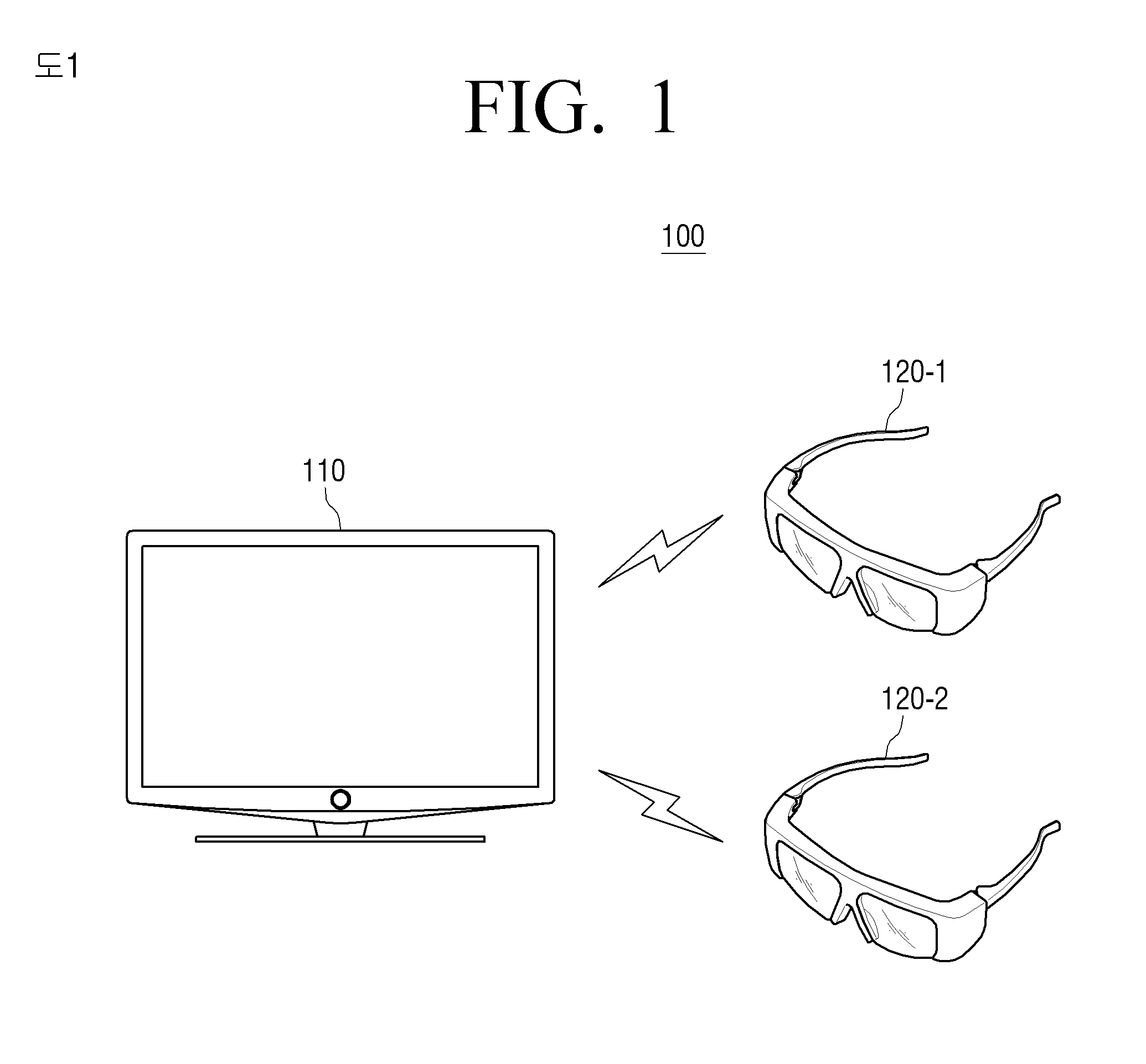
[0034]FIG. 1 is a diagram illustrating a 3D image providing system 100 according to an exemplary embodiment of the present disclosure. Referring to FIG. 1, the image providing system 100 includes a 3D display device 110 and glasses apparatuses 120-1 and 120-2, respectively.

[0035]The 3D display device 110 is a kind of display apparatus, which receives a 3D image that is received from an image capturing device such as a camera or a 3D image that is captured by a camera, edited / processed and output by a broadcasting station, and processes and displays the 3D image on the screen. In particular, the 3D display device 110 may process a left-eye image and a right-eye image with reference to the format of the 3D image, and make the processed left-eye image and right-eye image time-divided and alternately displayed. Further, the 3D display device 110 may gene...


PUM


Abstract

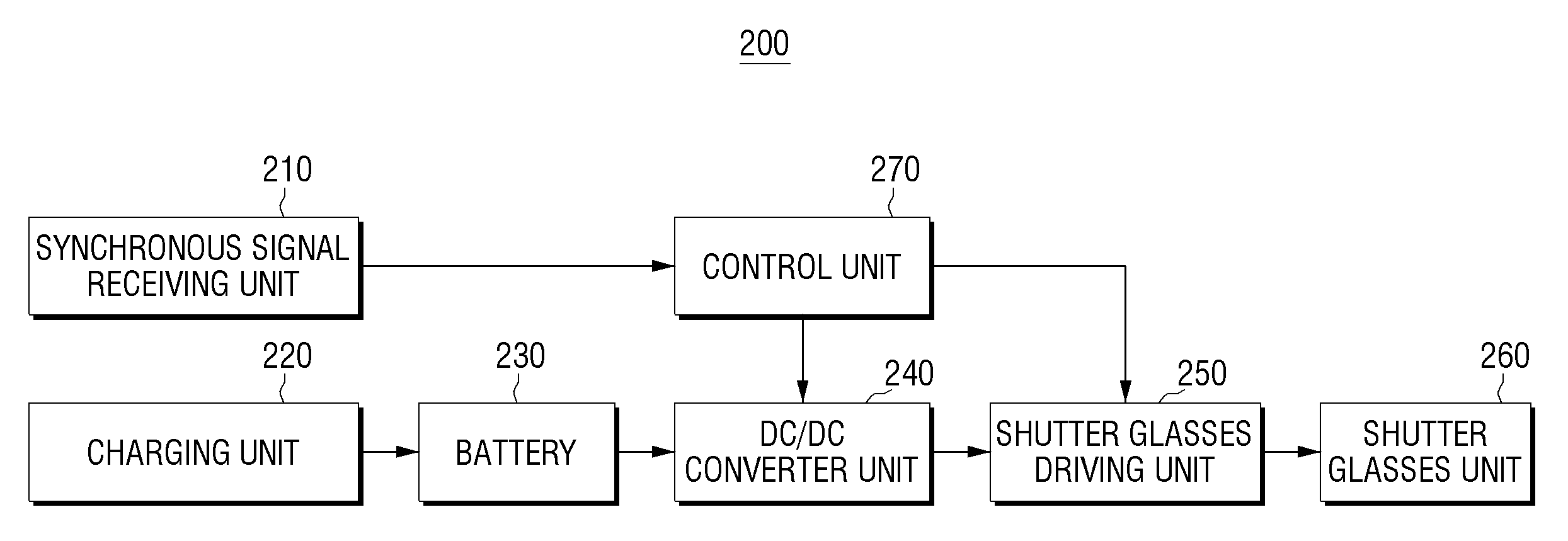
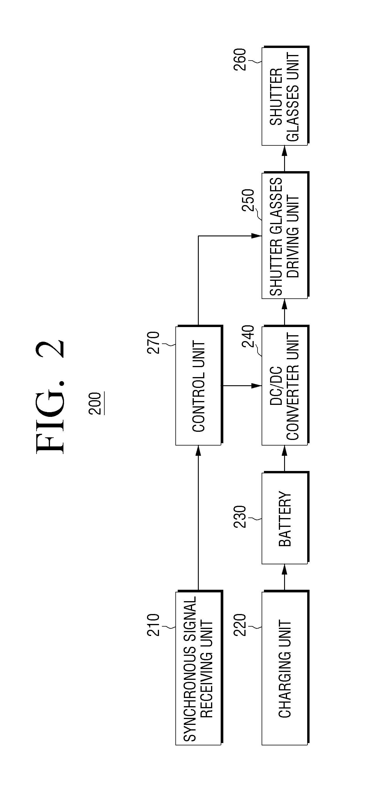
Glasses apparatus interlocking with a 3D display device is provided. The glasses apparatus includes a shutter glasses unit, a synchronous signal receiving unit receiving a synchronous signal from the 3D display device, a shutter glasses which drives unit driving the shutter glasses unit, a DC / DC converter unit which converts converting a DC voltage provided from a battery, and a control unit which controls the DC / DC converter unit to apply the converted DC voltage to the shutter glasses driving unit through supplying of a PWM signal to the DC / DC converter unit and controlling the shutter glasses driving unit, which is driven by the applied DC voltage, to turn on / off the shutter glasses unit according to the synchronous signal.

Description

PRIORITY[0001]This application claims priority under 35 U.S.C. §119(a) to Korean Patent Application No. 10-2012-6297, filed on Jan. 19, 2012 in the Korean Intellectual Property Office, the disclosure of which is incorporated herein by reference.BACKGROUND[0002]1. Field[0003]The present disclosure relates to glasses apparatus and a power supply apparatus. More particularly, the present disclosure relates to glasses apparatus that alternately display a left-eye image and a right-eye image, and a power supply apparatus.[0004]2. Description of the Related Art[0005]3D stereoscopic image technology has very diverse application fields, such as information communication, broadcasting, medical treatment, educational training, military affairs, games, animation, virtual reality, CAD, industrial technology, and the like. This may be the core basic technology of the next-generation 3D stereoscopic multimedia information communication which is commonly required in these fields.[0006]In general, ...

Claims


Application Information

Patent Timeline
Patent Type & Authority Patents(United States)
IPC IPC(8): G09G5/00
CPCH04N13/0497H04N13/0438G02B27/017G02B2027/0134G02B2027/0178G02B2027/014G06F1/3296H04N13/341H04N13/398G02B30/24Y02D10/00G02C1/06G02B30/00
Inventor WOO, WON-MYUNGLEE, JIN-HYUNG
Owner SAMSUNG ELECTRONICS CO LTD
Learn More