
Staged Hydrocarbon/Steam Reformer Apparatus And Method

Inactive Publication Date: 2009-04-23
AIR PROD & CHEM INC
View PDF10 Cites 8 Cited by
  • Summary
  • Abstract
  • Description
  • Claims
  • Application Information

AI Technical Summary

Benefits of technology

[0044]One of the primary advantages of the current invention is to enable a hydrogen production process to use a low overall or average steam-to-carbon ratio. The steam-to-carbon ratio is a key process parameter in hydrogen production processes. Lower steam-to-carbon ratio means lower heat loss in the process, and consequently, better thermal efficiency for hydrogen production. However, the process needs to maintain a minimum steam-to-carbon ratio to prevent carbon formation on the steam reforming catalyst (catalyst coking), which is detrimental to the operation. The current invention can help to lower this minimum steam-to-carbon ratio requirement.

Problems solved by technology

Prior art steam reforming apparatuses and methods suffer from various disadvantages.
For example, the problem of catalyst fouling due to carbon formation on the catalyst, known as “coking”, limits the efficiency of the process by limiting the minimum steam to carbon ratio of the process.

Method used


Image

  • Staged Hydrocarbon/Steam Reformer Apparatus And Method
  • Staged Hydrocarbon/Steam Reformer Apparatus And Method
  • Staged Hydrocarbon/Steam Reformer Apparatus And Method

Examples


example 1

[0052]This example relates to a one-stage convective reformer apparatus 100 shown in FIG. 11. The reformer has five parallel rows of tubes 102, 104, 106, 108, 110, each containing a methane reforming catalyst. The tubes are enclosed in a convection tunnel 112, and heated by the flue gas 114 from a fired reformer furnace (not shown). The flue gas 114 approaches the convective reformer at 836° C. and exits at 738° C. The tubes are arranged in a cross flow configuration with respect to the flue gas flow with the 5th row 110 being located upstream, 1st row 102 downstream, and the other three rows 104, 106 and 108 in between as shown. A feed 116 comprising methane and steam enters a distribution manifold 118 that is connected to the inlets of all five rows of tubes. The partially reformed gas 120 from the outlets of all tubes is collected by a collection manifold 122. This design is examined for a methane / steam feed 116 having a total of 3890 lbmol / hr methane and 9788 lbmol / hr steam. Thu...

example 2

[0055]This example relates to a two-stage convective hydrocarbon / steam reformer apparatus 124 shown in FIG. 12. The overall design is similar to that in Example 1. However, with respect to methane and steam flows, the two-stage design splits the five parallel row design in Example 1 into a first stage 126 comprising the first row of tubes 128 and a second stage 130 of the other four rows of tubes 132, 134, 136 and 138, with all tubes containing the same reforming catalyst. The overall feed flows 116a and 116b are the same as those in Example 1 comprising a total of 3890 lbmol / hr methane and 9788 lbmol / hr steam. Again, the overall steam-to-carbon ratio is 2.5. However, the feeds are distributed differently between the two stages. Twenty five percent of the total steam, 2447 lbmol / hr, is combined with 20% of the total methane, 778 lbmol / hr, and fed to the first reforming stage 126 as feed 116a. The remainder of the methane, 3112 lbmol / hr, and remainder of the steam, 7341 lbmol / hr, com...

example 3

[0057]This example relates to the same two-stage convective reformer apparatus 124 as described in Example 2. The only change is to decrease the total steam flow from 9788 to 9000 lbmol / hr, which decreases the overall steam-to-carbon ratio from 2.5 to 2.3. The percentage distribution of the methane and steam flows 116a and 116b to the two stages are the same as in Example 2. The resulting steam-to-carbon ratio of the fresh feed 116a to the first stage 126 is 2.9, and that of the fresh feed 116b to the second stage 130 is 2.2. This decrease in the overall steam-to-carbon ratio makes the CFIs at the inlets of all five rows of tubes in the two-stage convective reformer equal to or less than those in the one-stage convective reformer of Example 1. All conditions and results are shown in Table 3. Comparison of the results in Tables 1 and 3 shows that, for the same CFIs, or the same propensity or risk for carbon formation, the two-stage arrangement requires only an overall steam-to-carbon...


PUM


Abstract

A staged steam hydrocarbon reformer is disclosed having a chamber within which convectively heated reformer stages are enclosed. The reformer stages are tubes containing steam reforming catalyst. The stages are in serial fluid communication with one another through mixing vessels positioned between each stage. The first reforming stage is fed a mixture of steam and a gaseous hydrocarbon. Partially reformed gases having increased hydrogen concentration are produced at each stage and are mixed with additional gaseous hydrocarbon and optionally steam in the mixing vessels. Collection and distribution manifolds provide fluid communication between the reformer stages and the mixing vessels. A method is also disclosed in which partially reformed gases from a preceding stage are mixed with gaseous hydrocarbon and steam having a lower steam to carbon ratio than the fresh feed to the previous stage.

Description

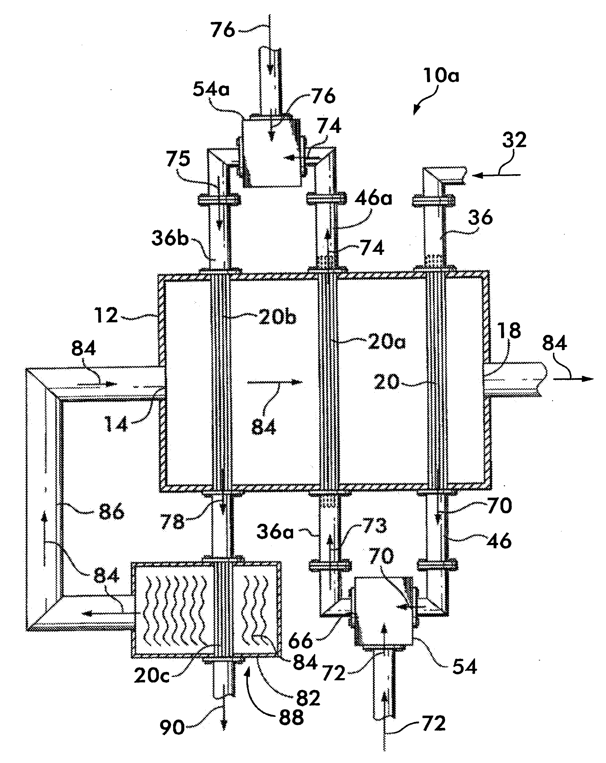
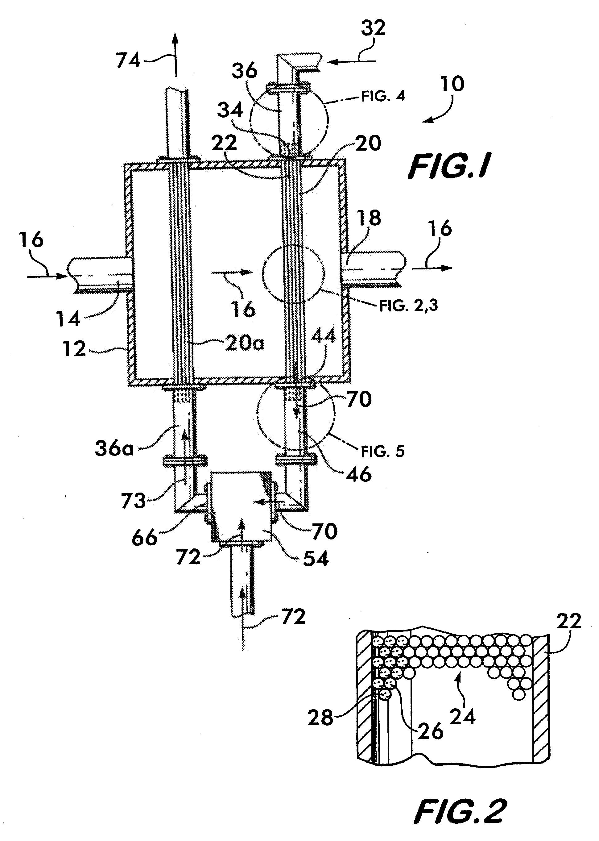
BACKGROUND OF THE INVENTION[0001]This invention relates to an apparatus and method for steam reforming of gaseous hydrocarbons to form a synthesis gas comprising hydrogen.[0002]Hydrogen may be produced from hydrocarbons contained in compounds such as gasified coal, coke, oil, and oil refinery waste products as well as natural gas, biogas and other compounds using a hydrogen reforming process. A well known example of this process is steam methane reforming, wherein methane and steam are reacted at temperatures between about 400° C. and about 1000° C. in the presence of a metal catalyst to yield a synthesis gas comprising carbon monoxide and hydrogen as described in the chemical equation CH4+H2O→CO+3H2. A part of the carbon monoxide thus produced may be further converted to hydrogen and carbon dioxide by the water gas shift reaction as described in the chemical equation CO+H2O→CO2+H2 to further increase the hydrogen content of the synthesis gas. The synthesis gas containing hydrogen a...

Claims


Application Information

Patent Timeline
IPC IPC(8): C01B3/26B01J19/00
CPCB01J8/008C01B2203/82B01J8/067B01J2208/00309B01J2208/0053B01J2208/00849B01J2219/0277C01B3/382C01B3/384C01B2203/0233C01B2203/042C01B2203/0811C01B2203/0822C01B2203/0827C01B2203/0833C01B2203/1058C01B2203/1235C01B2203/1241C01B2203/1282C01B2203/142C01B2203/143B01J8/062Y02P20/10
Inventor PENG, XIANG-DONGREPASKY, JOHN MICHAELHERB, BLAINE EDWARD
Owner AIR PROD & CHEM INC
Learn More