
Prosthetic limb with replaceable fairing

a prosthetic limb and fairing technology, applied in non-surgical orthopedic devices, instruments, medical science, etc., can solve the problems of less thought given to the aesthetics of the human being for whom the device was intended, neglecting the fundamental symmetry of the human form, and asymmetric appearance of the prosthetic limbs are more troublesome than physical discomfort, so as to achieve easy change, improve the appearance of a portion, and improve the strength of the prosthetic limb

Active Publication Date: 2009-04-09
3D SYST INC
View PDF9 Cites 20 Cited by
  • Summary
  • Abstract
  • Description
  • Claims
  • Application Information

AI Technical Summary

Benefits of technology

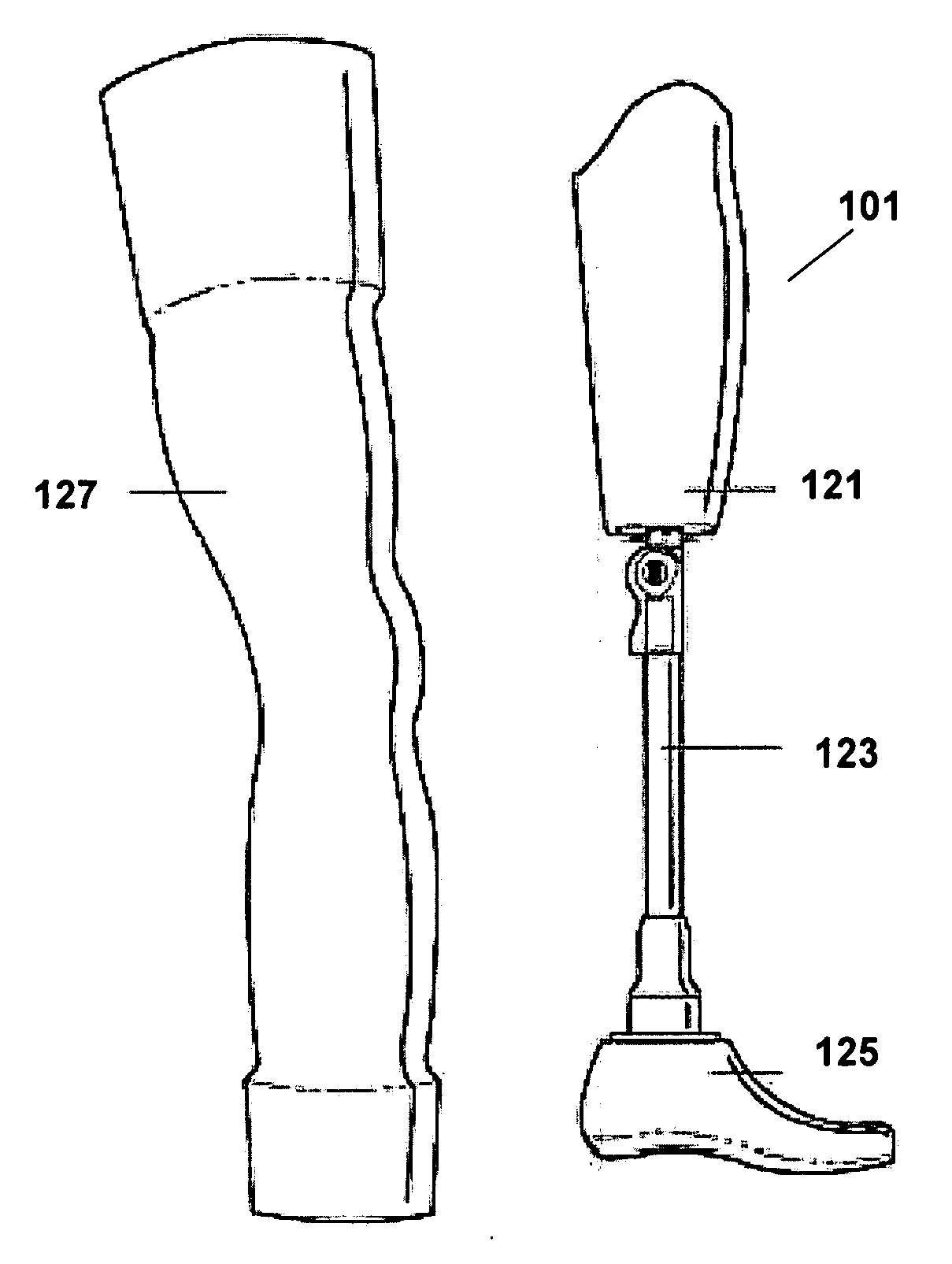
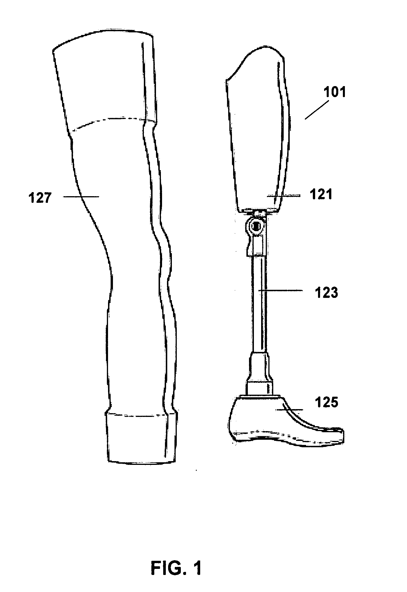
[0012]The prosthetist uses the CAD based application to combine the leg surface data with socket and foot data to create a complete virtual prosthetic leg that is displayed on the computer. The GUI can allow the prosthetic leg components to be easily changed using integrated design tools. These GUI controls can allow the prosthetic designer to alter the prosthetic design in various ways to customize various attributes of the design within parameters designated by variables built into a leg template. A GUI tool can be used, for example, to change the foot component used with the leg. The GUI tool can also be used to modify the leg to include specific colors, textures and surface features. Thus, the user can create a prosthetic leg that is substantially a mirror image to the intact leg or create a leg that is very different in appearance.
[0013]In an embodiment, the prosthetic leg can also include a fairing that is a removable layer that covers a portion of the prosthetic leg. The user can specify the aesthetic attributes of the fairings which can also be removed or replaced The user can also alter the appearance of a portion of the prosthetic leg. The appearance of the fairing and leg can be easily changed as desired by the user. The CAD system can also allow the user, the prosthetic designer and the prosthetist to view the prosthetic leg with various fairing designs. For example, the GUI can include a fairing material controller that allows the user to see many virtual fairings made from a variety of materials including: metals, plastics, fabrics, leather, etc. The prosthetic designer can also use the CAD system to select the attachment mechanism for the fairing. The attachment mechanism can include adhesives, fasteners, magnets, etc The fairing must be securely attached to the prosthetic leg to remain attached during normal physical activities. The CAD system is particularly useful because it allows the user to design and view any desired combination of features and fairings prior to fabrication.
[0014]In addition to the physical appearance, the prosthetic leg must also be strong enough for the required use. A prosthetic leg must be able to support the user's weight and impact while running or jumping and a prosthetic arm must be able to withstand the normal use forces. In an embodiment, the strength of the prosthetic limb can be provided by internal structures such as a load bearing pylon. An outer surface that is not load bearing can be attached around the load bearing pylon. Alternatively, the load bearing structure can be a much larger volume component that not only has a load bearing core that connects the knee component to the foot component and expands outward so that it creates a sense of the volume defined by the original leg. In order to create a lighter structure, void space can exist within the outer surface. The space between the pylon and outer surface can be a lattice, a series of ribs, a channel, or any sculptural element that may function to reduce weight, enhance appearance, and create the sense of leg volume and shape. In other embodiments, the limb is fabricated with the outer surface functioning as a load bearing member. Because the materials used to fabricate the prosthetic limbs are very strong, the system can be used to design a template, an external surface that is a thin wall and an internal structure that adequately supports the expected loads and the outer surface wall.
[0020]The fairing fabrication method will depend upon the selected materials and design. If the fairing is made of a thin flexible material such as leather, the fairing design data can be used by a computer controlled cutting machine to precisely cut the fairing material to the design shape. Alternatively, the fairing can be fabricated from a flexible plastic material or sheet metal to form a three dimensional fairing that can match the contours of the outer surface of the prosthetic leg using the rapid prototyping methods described above. It is also possible to combine different fairing components and customizing the appearance of the cosmetic fairing components. For example, a curved plastic fairing can be covered with a thin flexible material such as leather.

Problems solved by technology

While the engineering and mechanics of prosthetic limbs have evolved greatly, very little thought has been given to the aesthetics of the human being for whom the device was intended.
A problem with the existing prosthetics is that they neglect the fundamental symmetry of the human form.
For many amputees the asymmetric appearance of the prosthetic limb is more troublesome than their physical discomfort.
Because the components are not specifically designed for left or right sides of the body or have the appearance of a human leg, the components cannot have a symmetric appearance.
Efforts to improve the appearance with a flesh colored electrometric foam cover 127 are also problematic.

Method used


Image

  • Prosthetic limb with replaceable fairing
  • Prosthetic limb with replaceable fairing
  • Prosthetic limb with replaceable fairing

Examples


Embodiment Construction

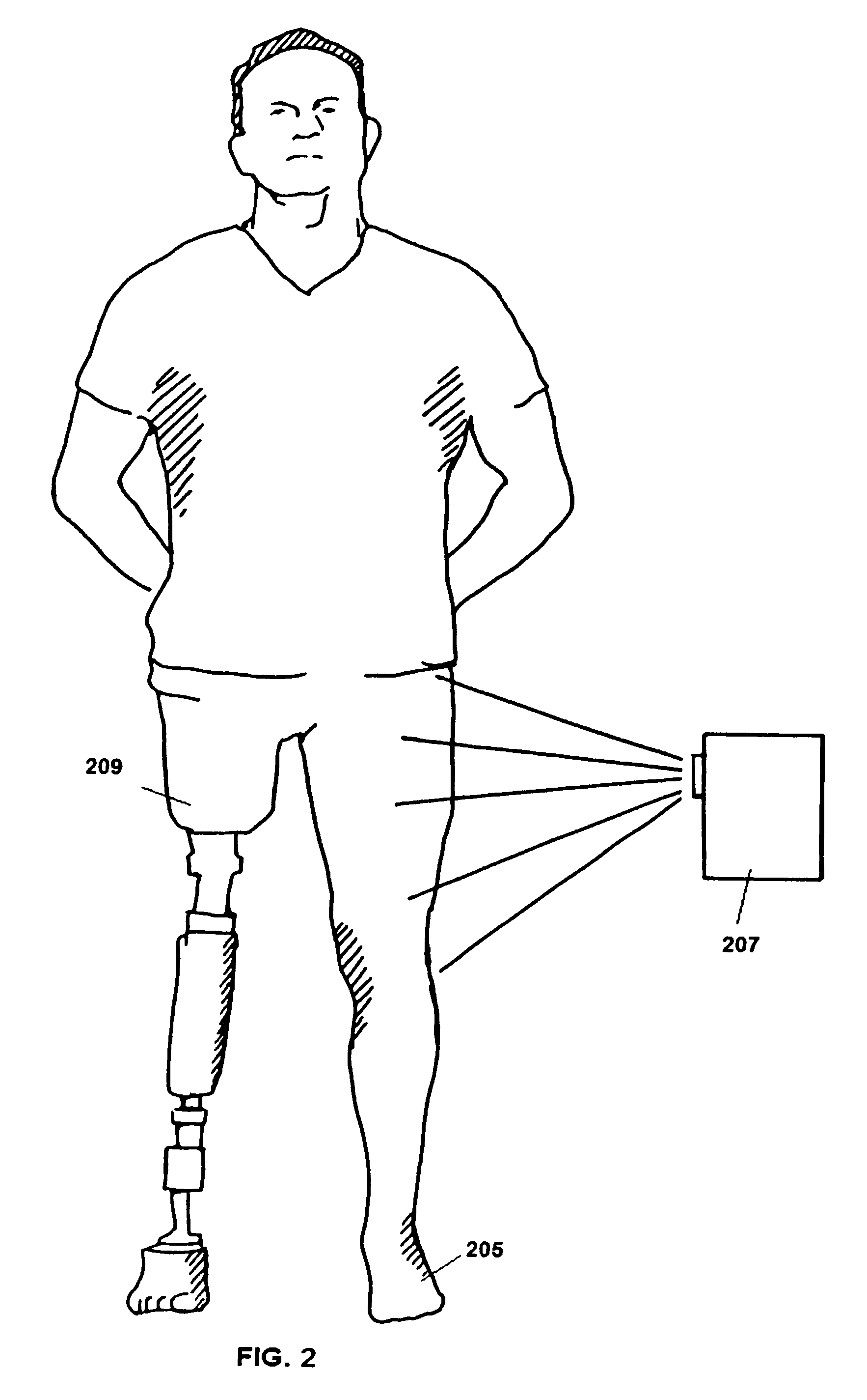
[0036]The present invention is a prosthetic limb having an exterior surface that matches the surface contours of a human limb. The prosthetic limb emulates the contours of the original limb by referencing surface geometry drawn from the sound side limb. The exterior surface can also be modified so a user can alter the appearance of the prosthetic limb. A replaceable fairing can be designed to cover a portion of the prosthetic limb. The prosthetic limb and fairing are designed on a computer and the design data can be used to fabricate the prosthetic components using computer controlled fabrication machines. The inventive prosthetic limb is primarily directed towards prosthetic legs but the same design and fabrication processes can also be used to create prosthetic arms. The prosthetic limb is preferably designed by an industrial designer using a Computer Aided design (CAD) program.

[0037]The inventive prosthetic legs include a load bearing component that functions as the human tibia. ...


PUM


Abstract

A prosthetic limb has an outer surface that is a mirror image of an intact limb. The intact limb is scanned and the surface data is manipulated to create a virtual mirror image. The end of the amputated limb is also scanned to obtain socket data. A virtual limb is designed using a computer program based upon the mirror image and end of the amputated limb data. The computer program is also used to design a removable fairing that provides color and texture to the prosthetic limb.

Description

BACKGROUND[0001]A prosthesis limb replaces a missing extremity, such as an arm or a leg and may be needed for a variety of reasons, including diseases, and accidents. An artificial limb may also be needed when a person is born with a missing or damaged limb(s). The type of prosthesis limb used is determined largely by the extent of an amputation or loss and location of the missing limb. A transtibial prosthesis is an artificial leg that is attached to a user below the knee and includes a lower leg, ankle and foot. The transfemoral prosthesis is an artificial leg that is attached to the user's amputated limb above the knee and includes an upper leg and mechanical knee. A transradial prosthesis is an artificial arm that is attached to the user below the elbow and includes a forearm and hand. A transhumeral prosthesis is an artificial arm that is attached to the user above the elbow.[0002]In developing areas of the world, including large portions of Africa, the leading causes of amputa...

Claims


Application Information

Patent Timeline
Patent Type & Authority Applications(United States)
IPC IPC(8): A61F2/74A61F5/00
CPCA61F2/5046A61F2/60A61F2002/505A61F2002/5001A61F2002/5049A61F2/64B33Y50/00B33Y80/00
Inventor SUMMIT, SCOTT
Owner 3D SYST INC
Learn More